Choose an activity below:
Initial Assembly Quest Weather Training USB Charge Module
Initial Assembly
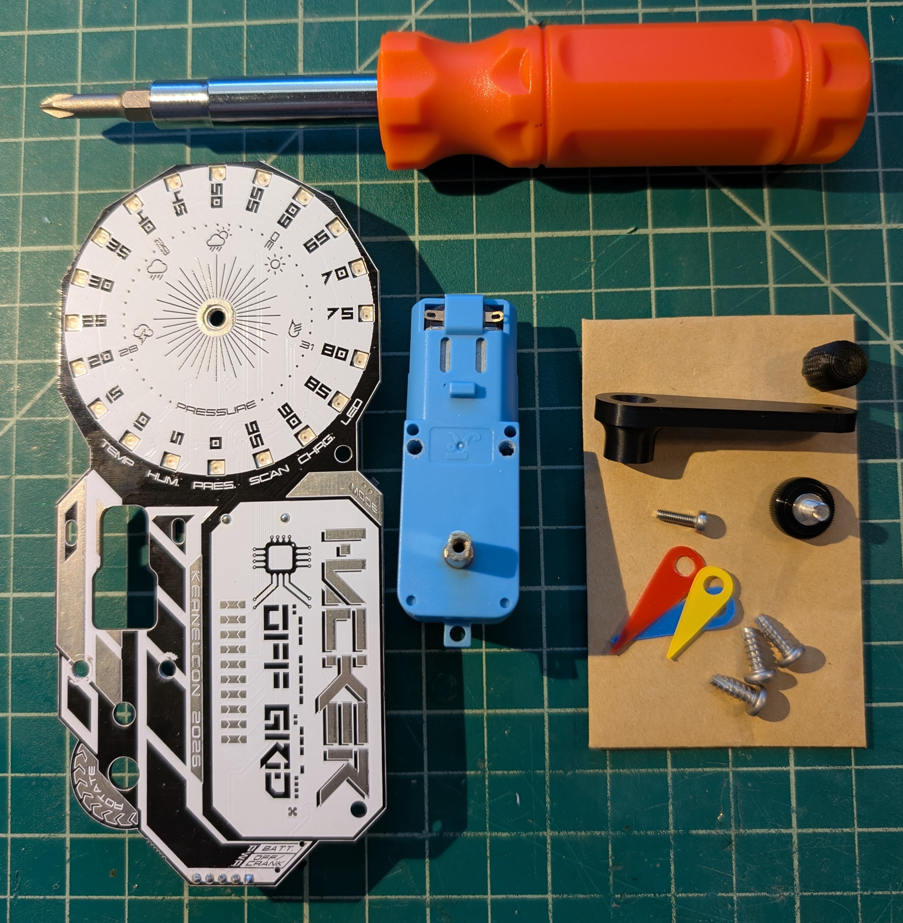
First, gather your parts from your badge bag:
- 3x - #6 x 3/8" screws (larger, pointed tip, coarse threads)
- 1x - M2.5 x 8mm bolt (smaller, flat tip, fine threads)
- 1x - thumb screw
- 1x - crank knob
- 1x - crank arm
- 1x - motor assembly
- 3x - weather reading dials (1 of each color)
The only tool needed is a screwdriver, which are available at assembly tables near registartion and in the Badge Village.
Motor to PCB Assembly
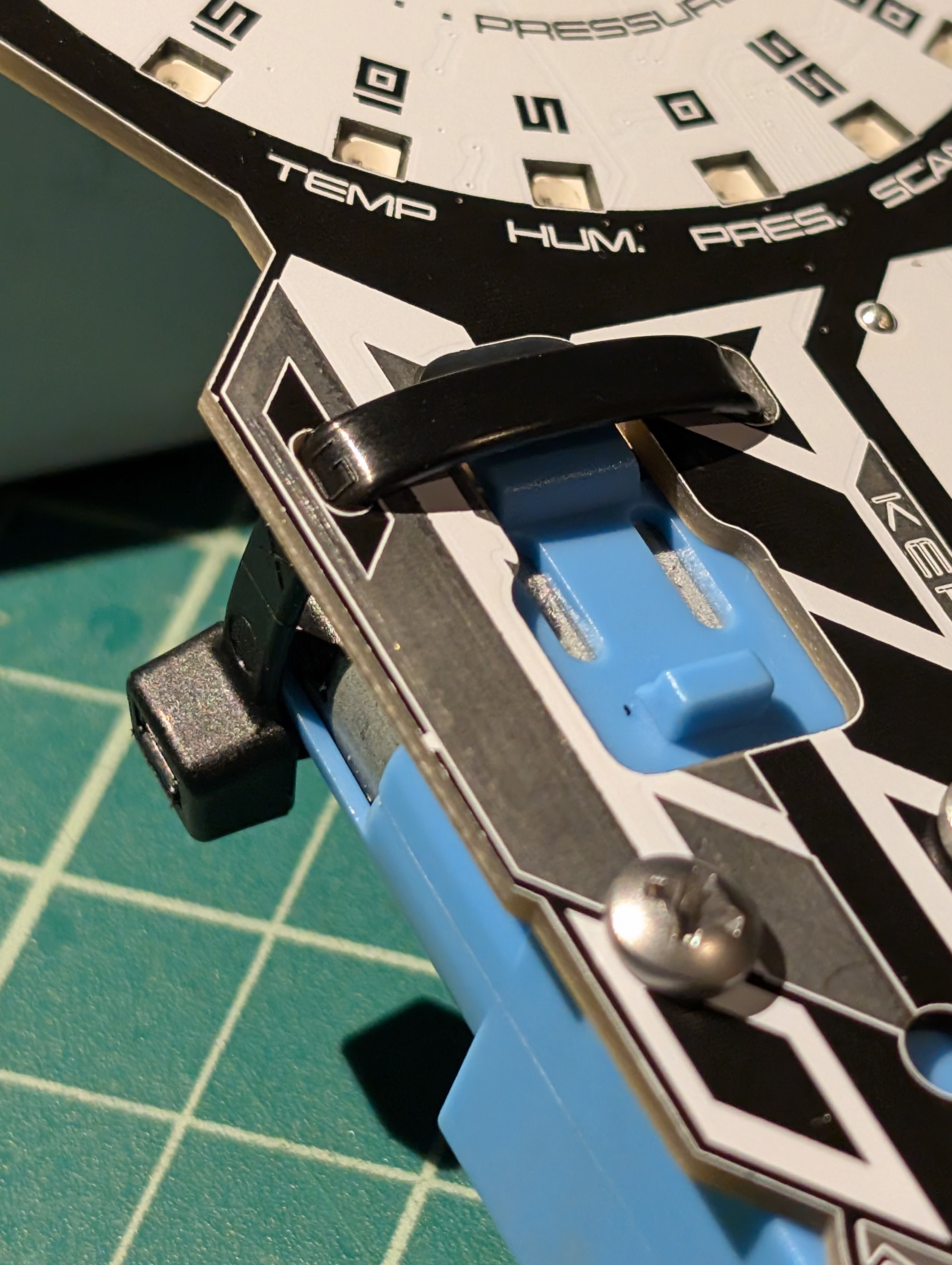
Bend the connection tabs of the motor from their flat position to approximately a 45-degree angle upward—this helps them make good contact when assembled.
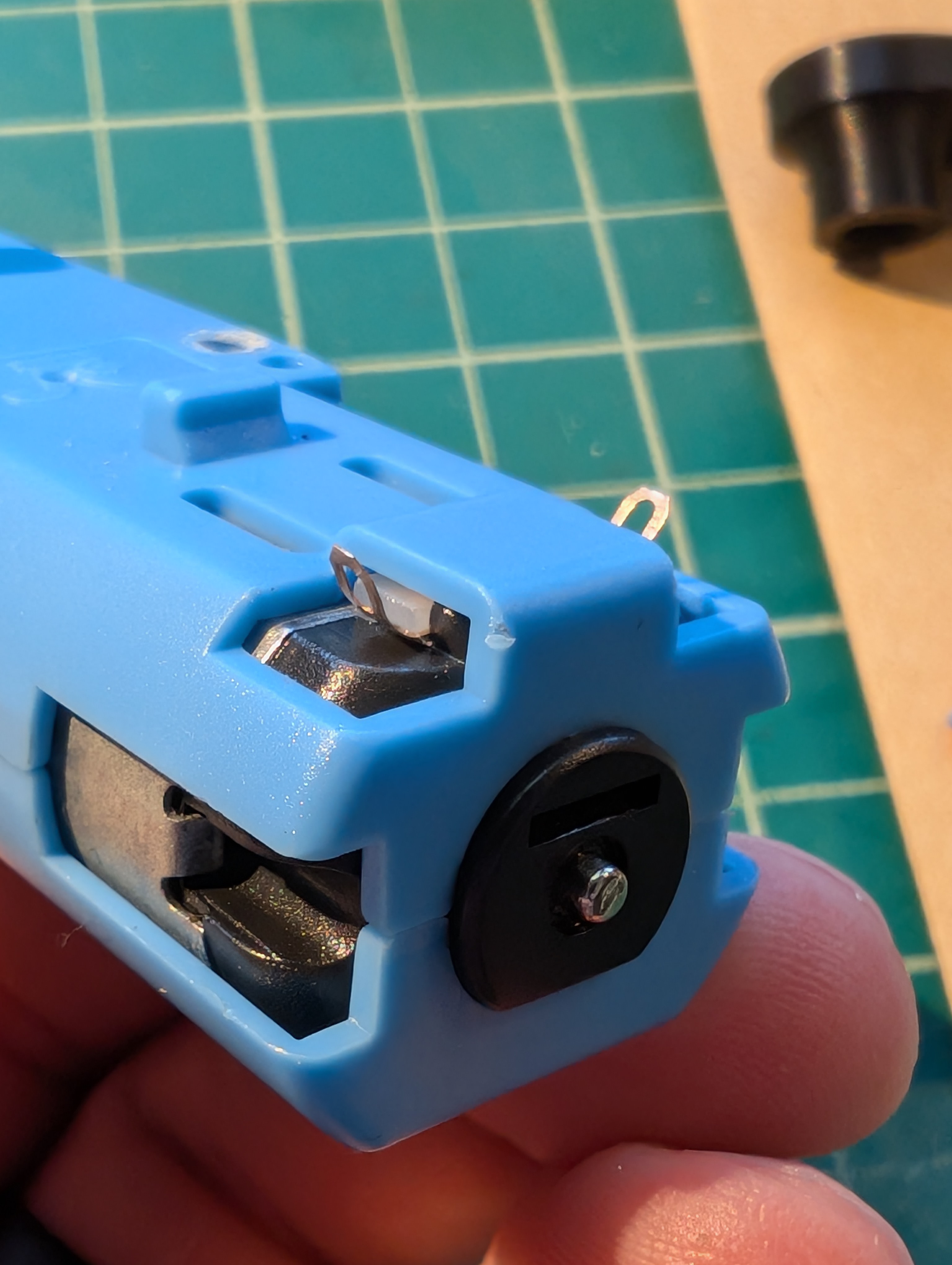
Next, position the motor on the back of the PCB. The motor connection tabs should be facing the large contact pads on the PCB.
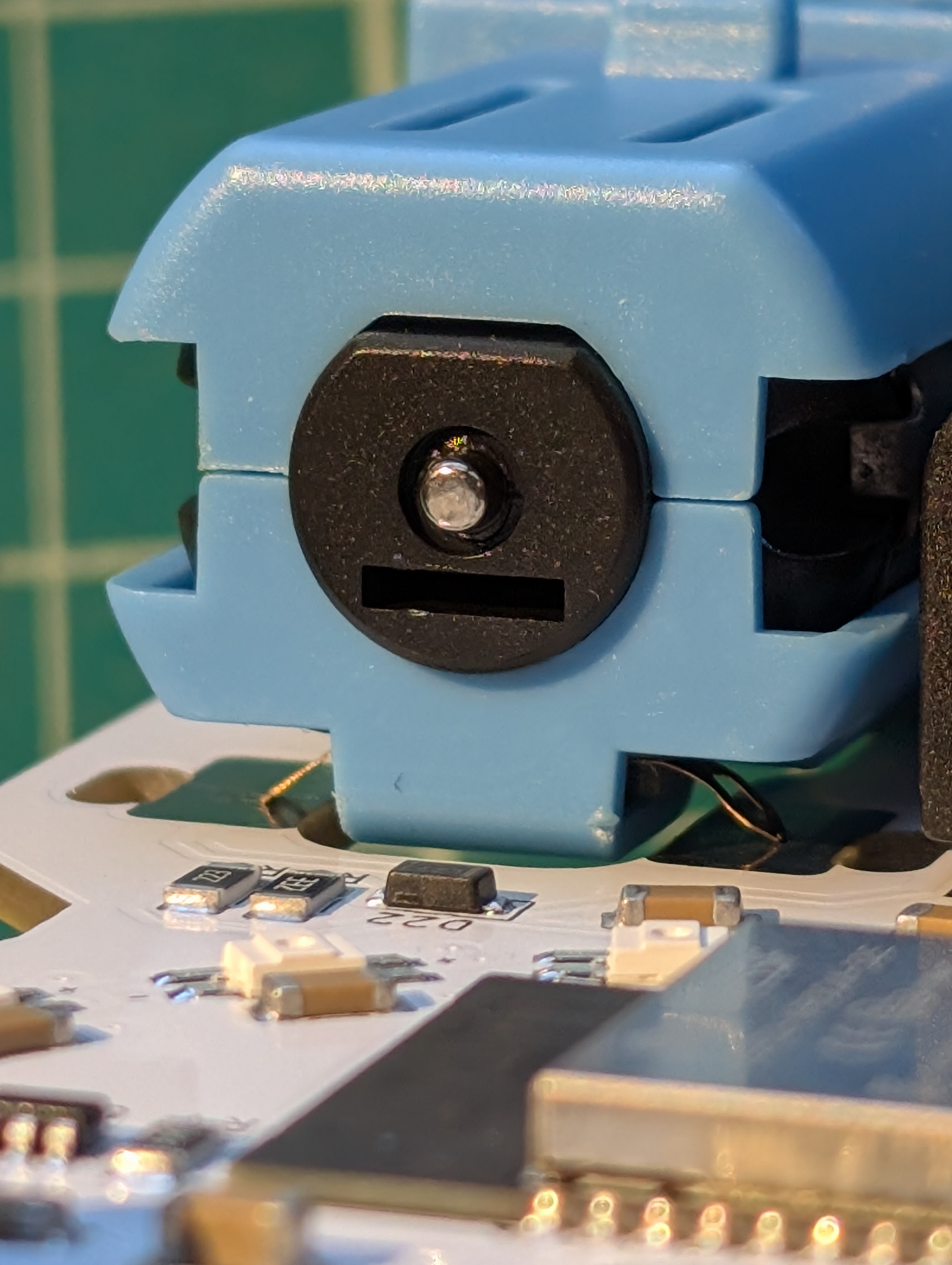
While holding the motor in place, flip the board over so you can install the screws. Insert 2x of the #6 screws (larger, pointed tip, coarse threads) from the front of the PCB into the motor, ensuring the connection tabs and pads make contact. Tighten them securely.
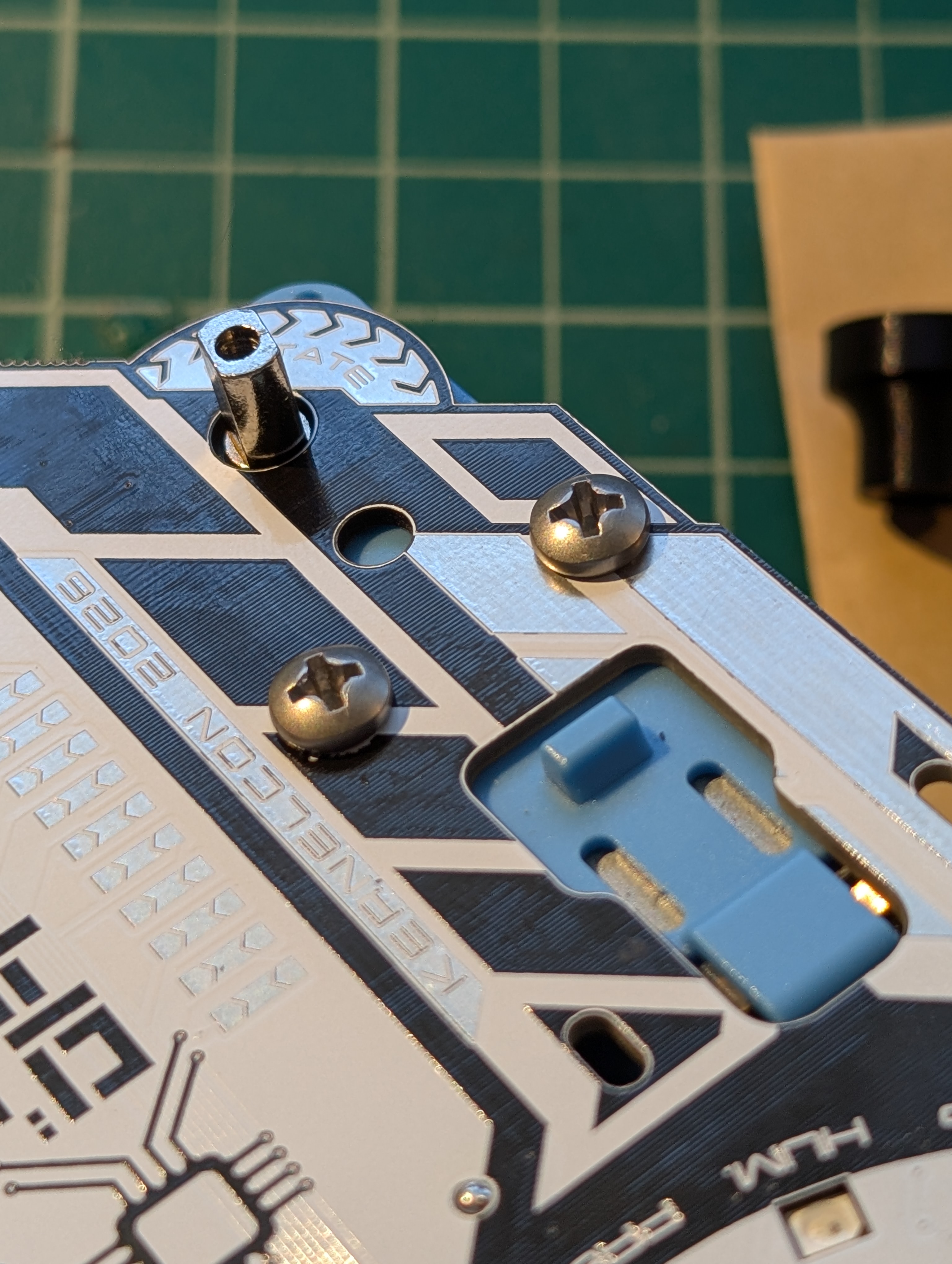
After tightening the screws, verify that the motor connection tabs are making good contact with the pads on the PCB.
Optional: If desired, a zip tie can be used to further secure the motor's electrical connectors to the PCB pads.
Crank Assembly
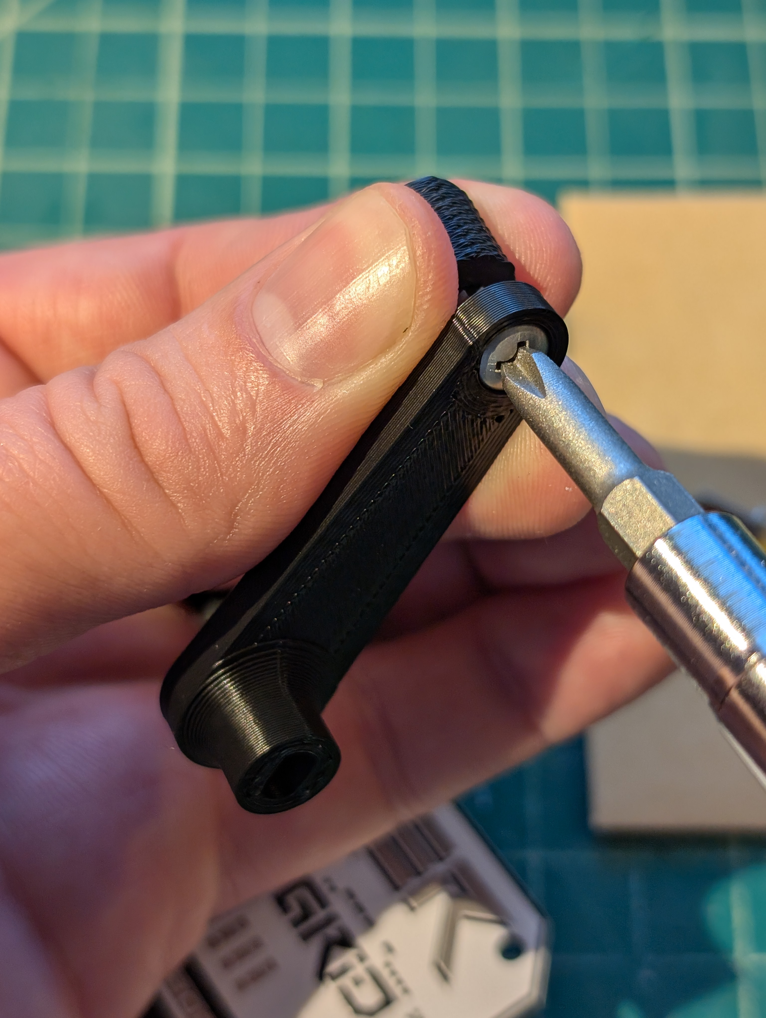
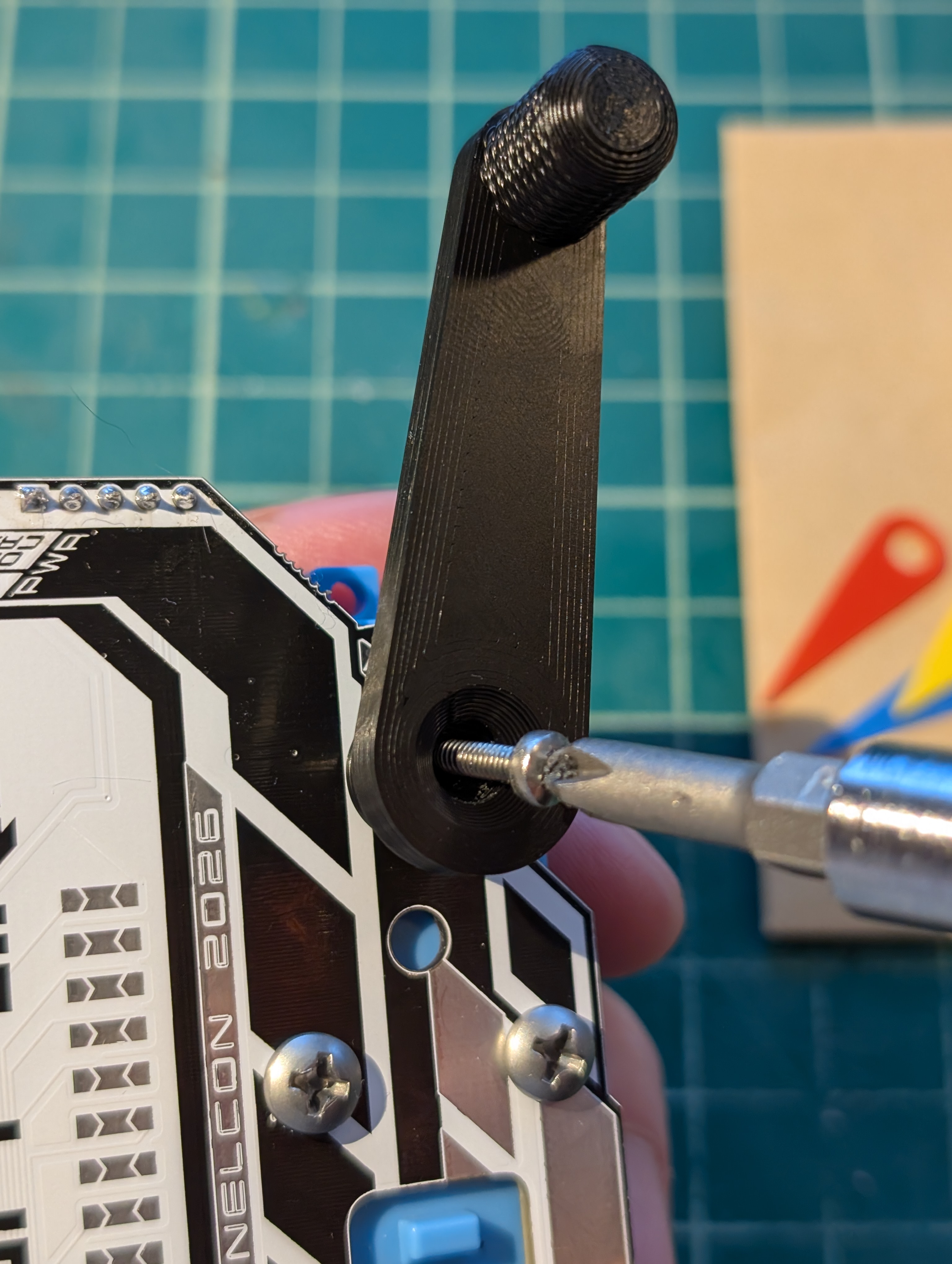
First, attach the crank knob to the crank arm using a #6 screw (larger, pointed tip, coarse threads)—the same type used to mount the motor. The M2.5 bolt (smaller, flat tip, fine threads) will be used later. Note the recess in the part designed for the screw head—this confirms correct orientation. Tighten the screw fully; the hole depth is designed to leave the proper gap for free rotation.
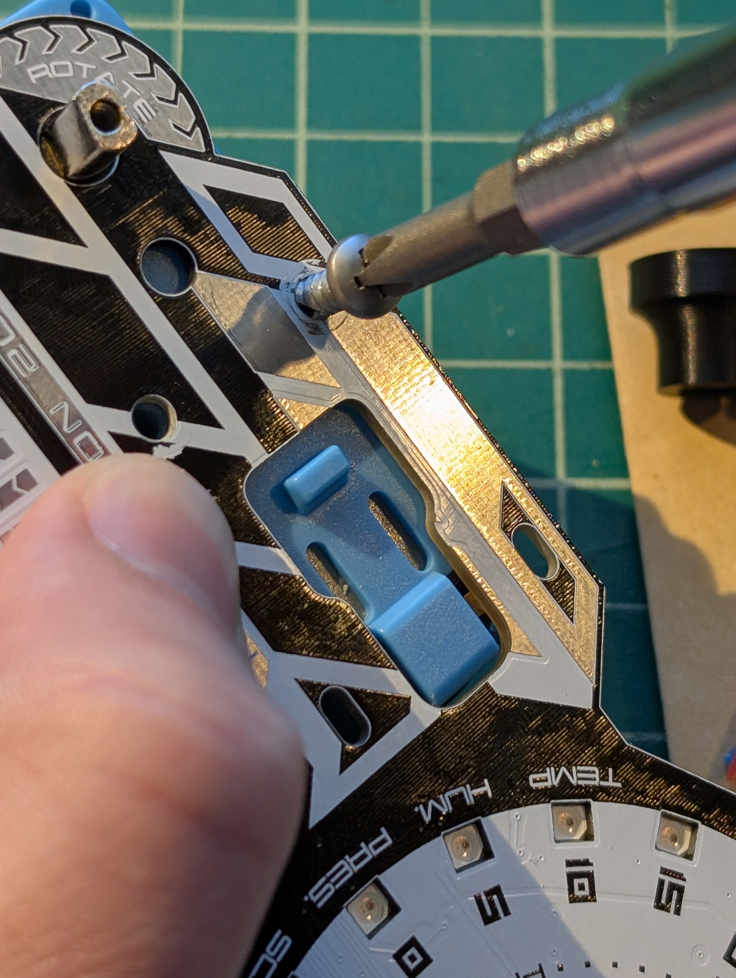
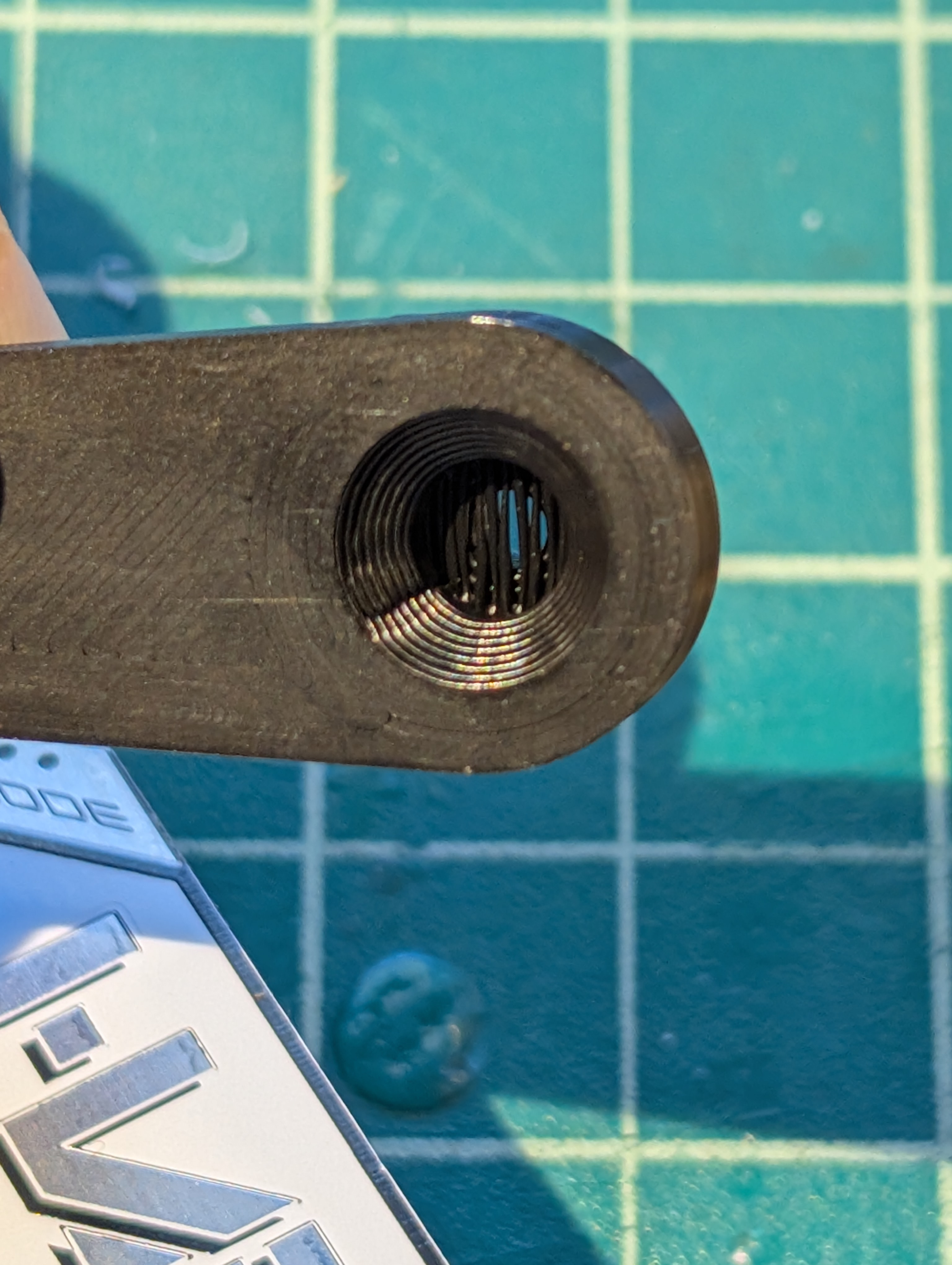
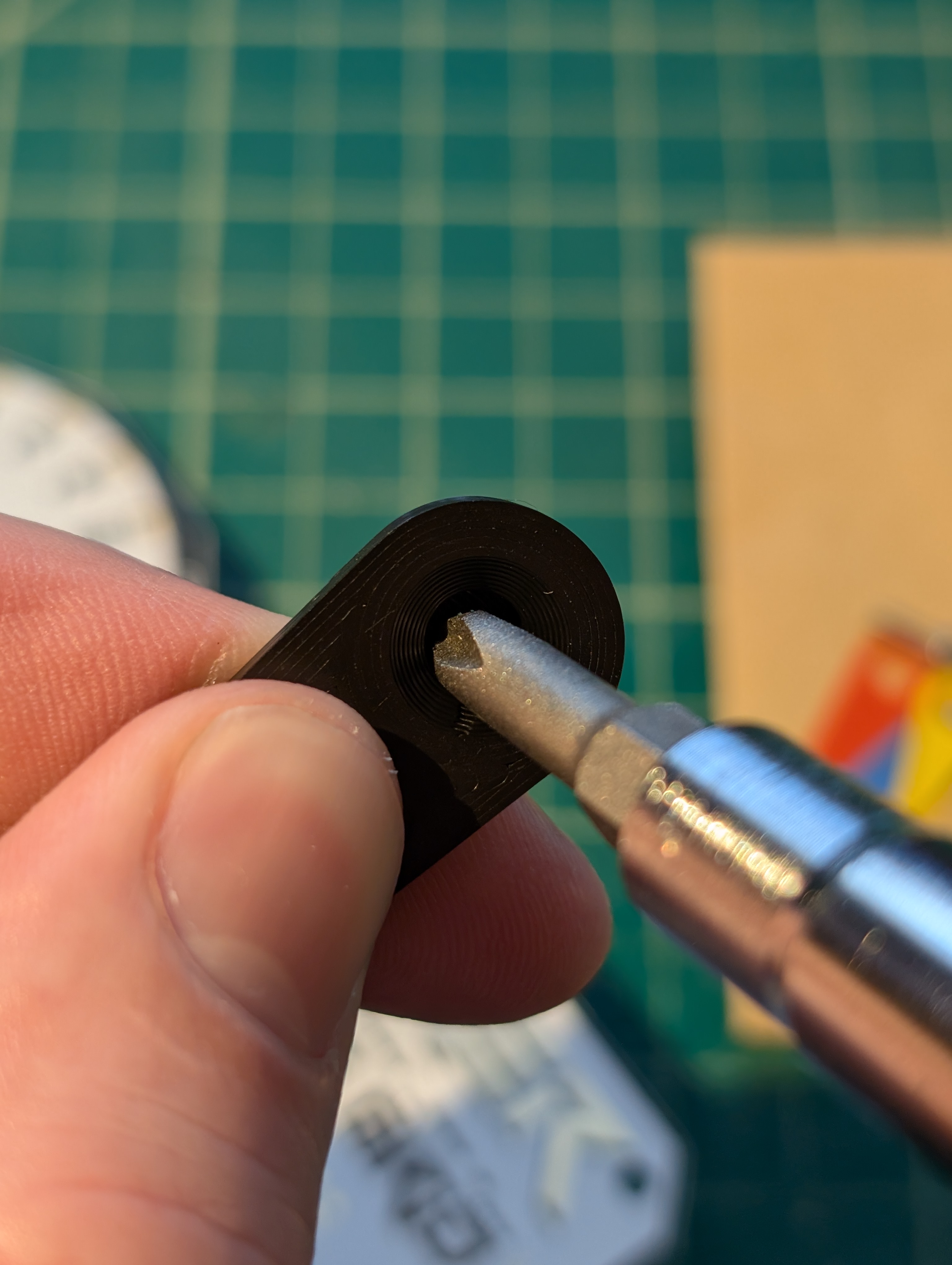
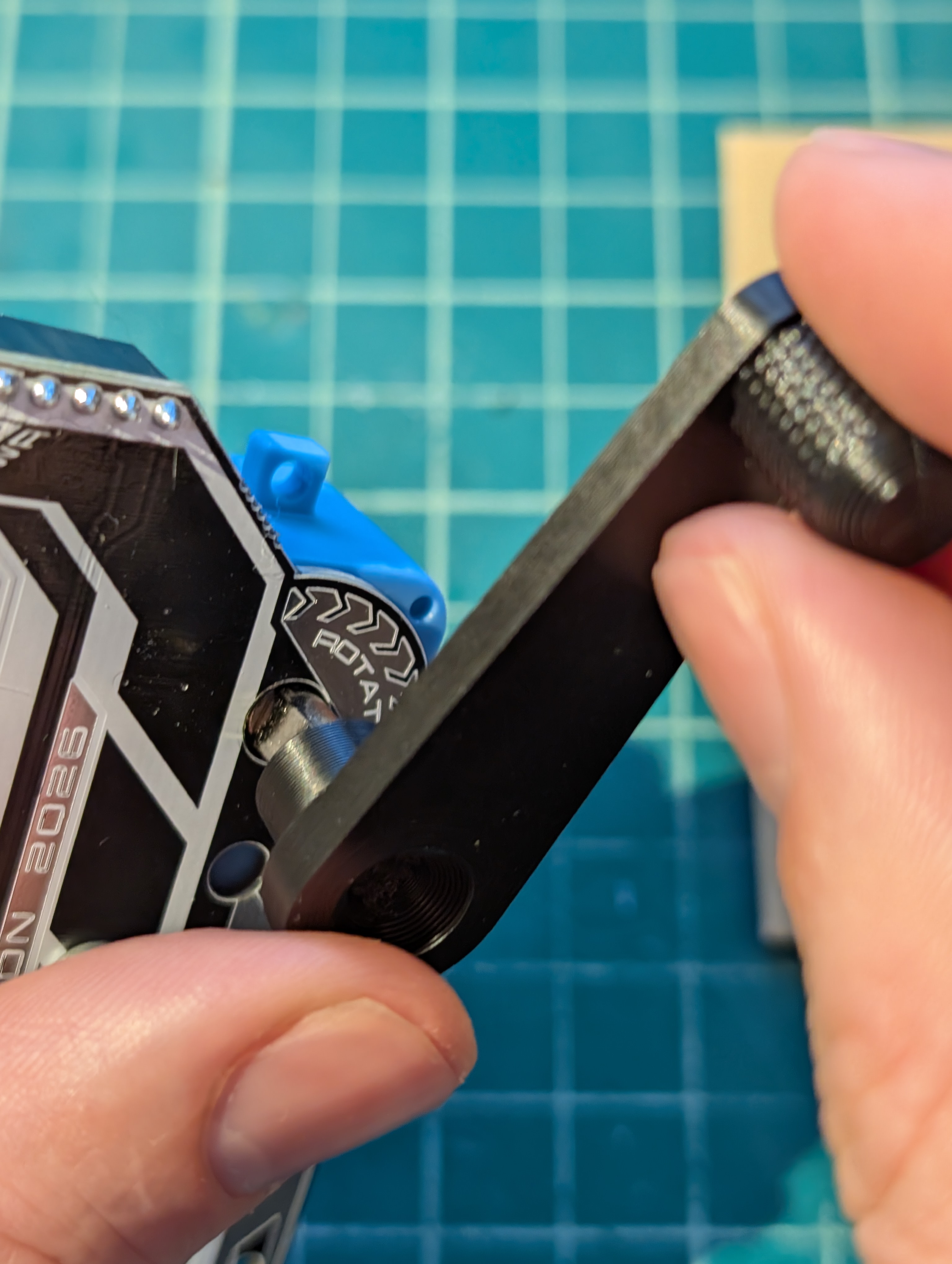
The 3D print uses a "sacrificial bridge" that needs to be punched open. Use the tip of the screwdriver to open it. Push and twist.
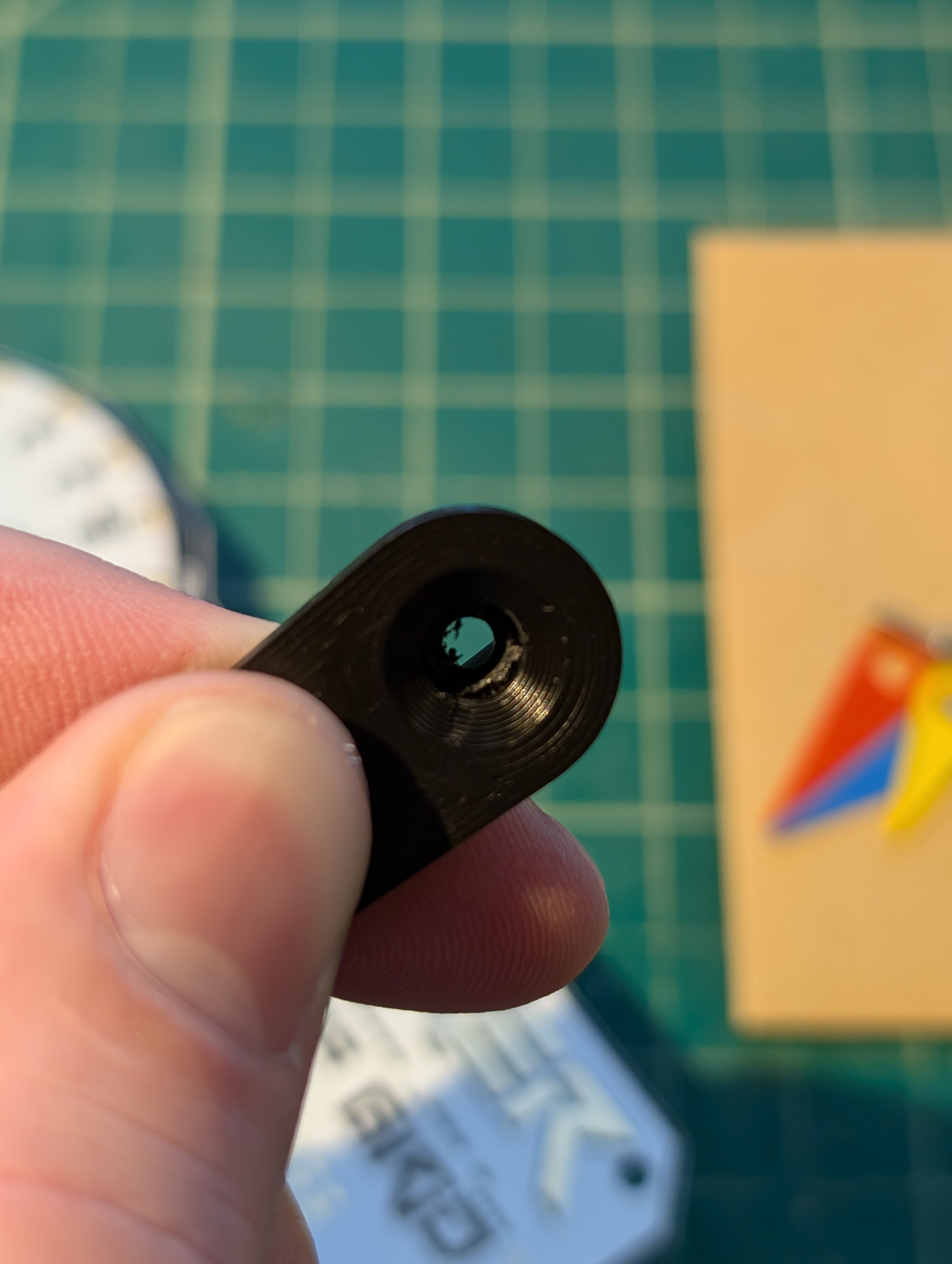
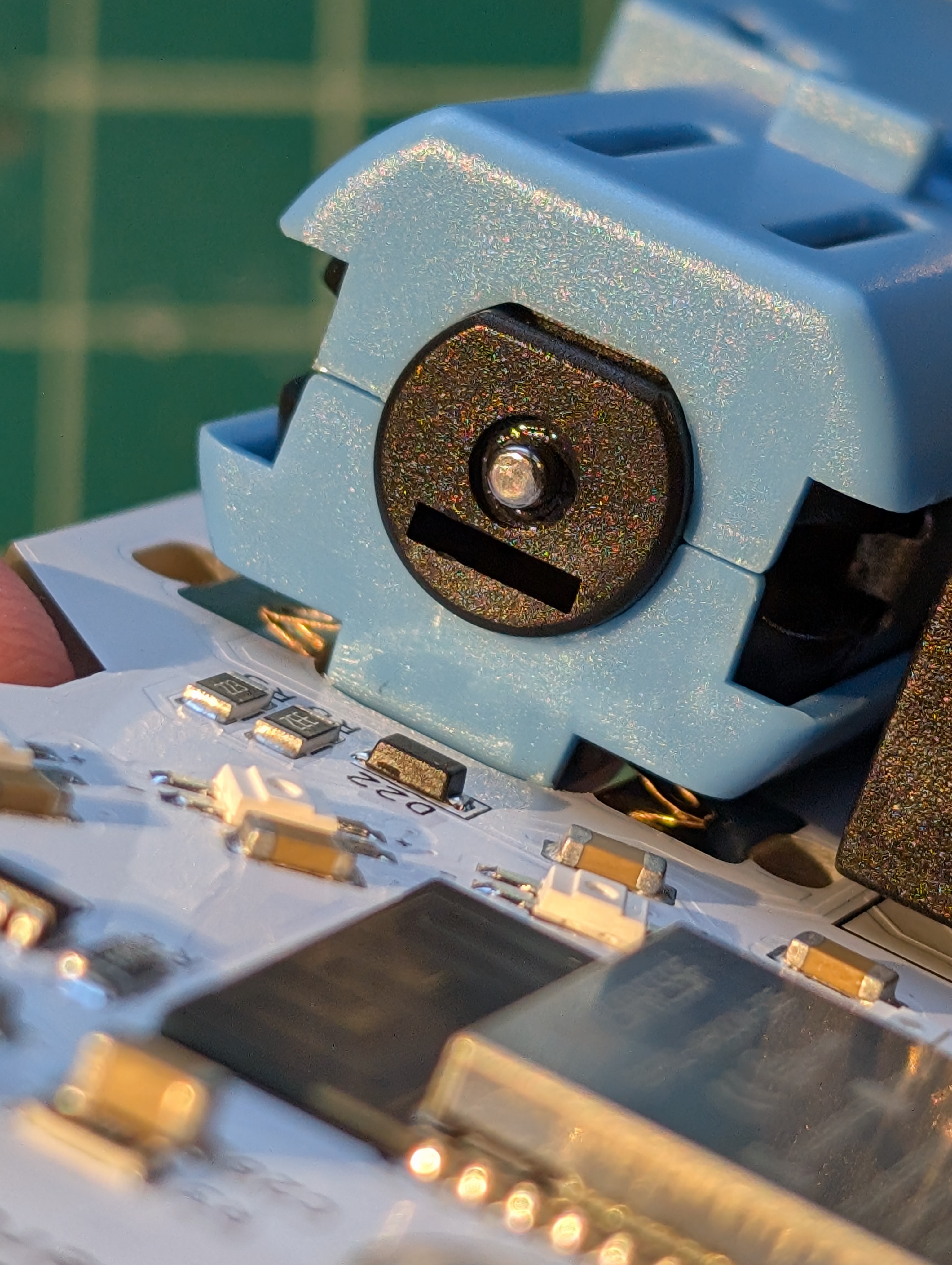
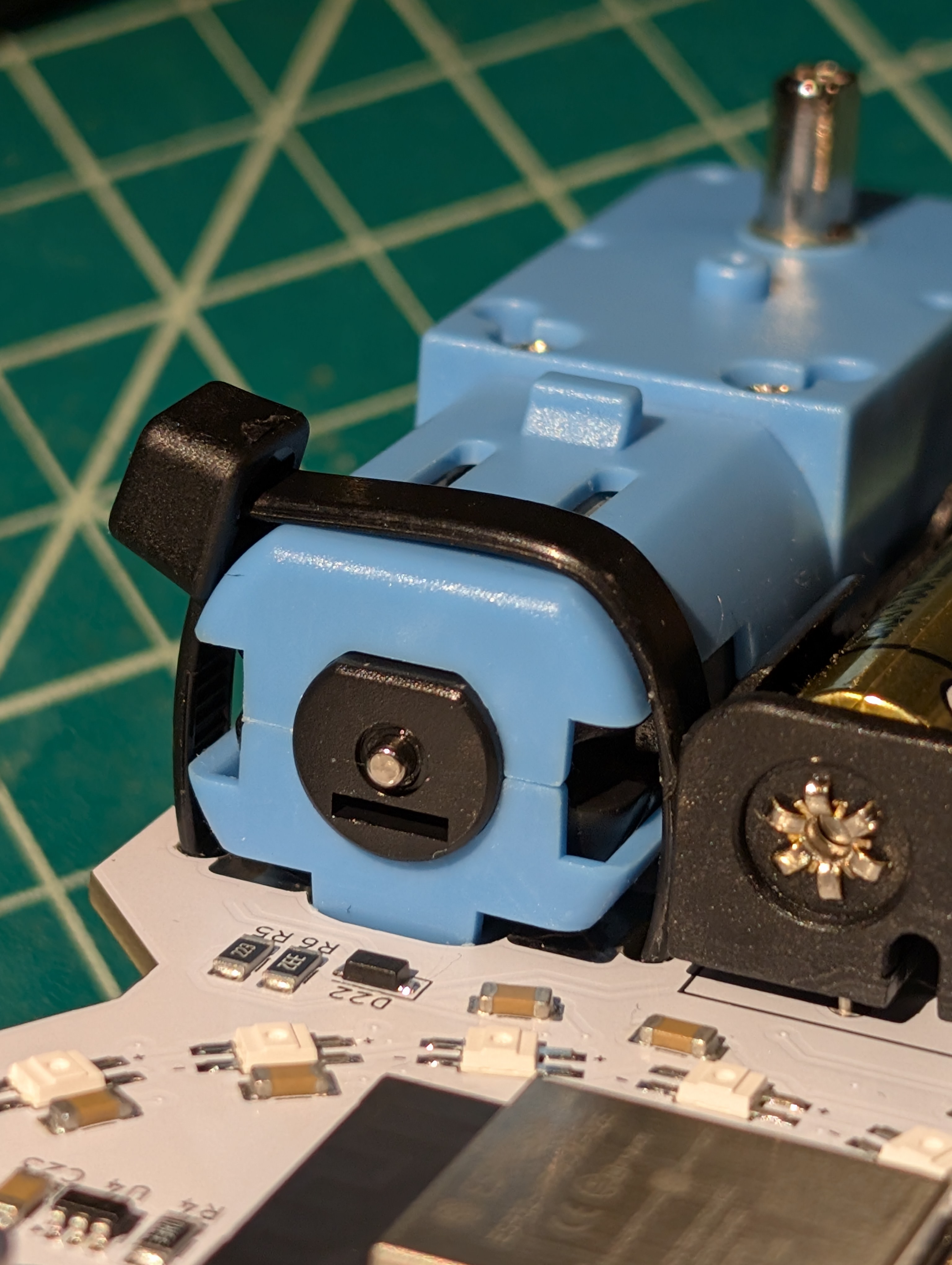
Next, note the shape of the motor shaft and the complementary hole on the crank arm. Push the crank into position, ensuring the shapes are aligned.
Finally, secure the crank to the motor shaft using the M2.5 bolt (smaller, flat tip, fine threads).
Weather Reading Dial Assembly
First, place all 3 colored dials onto the thumb screw in any order.
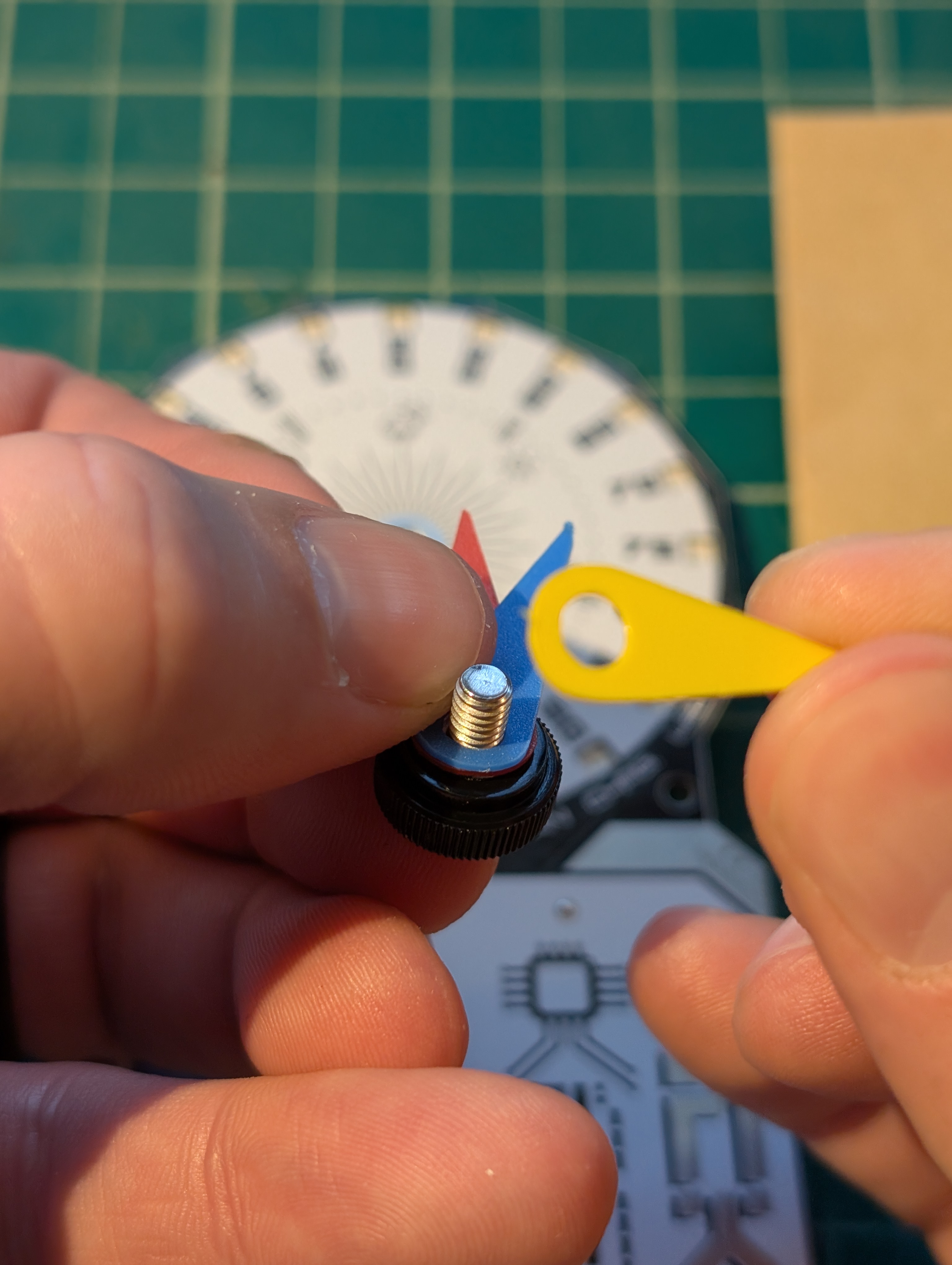
Then, screw the thumb screw into the threaded hole at the center of the circle (technically a dodecagon-ish shape). The thumb screw only needs to be snug—just enough that the dials can hold their readings.
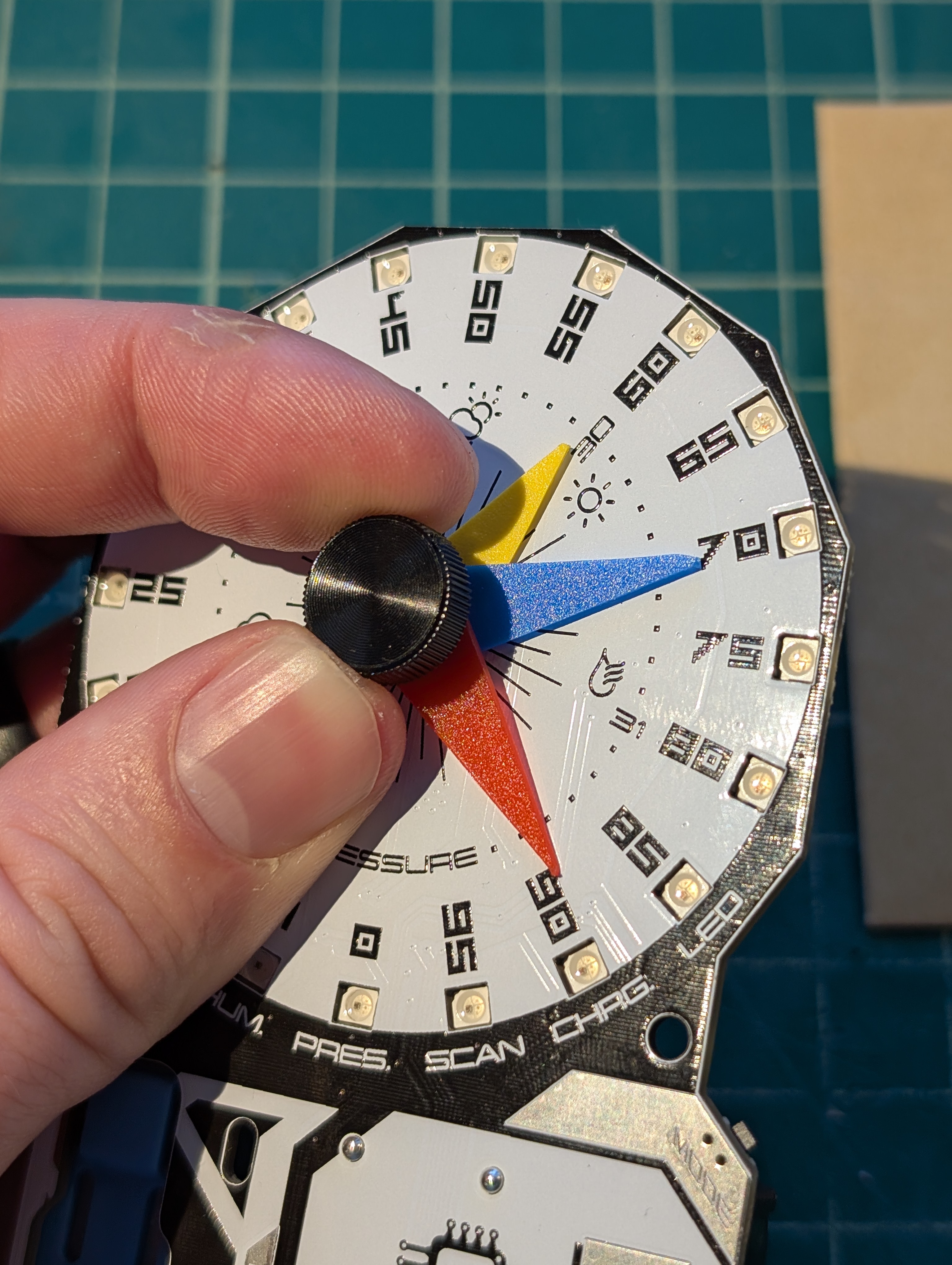
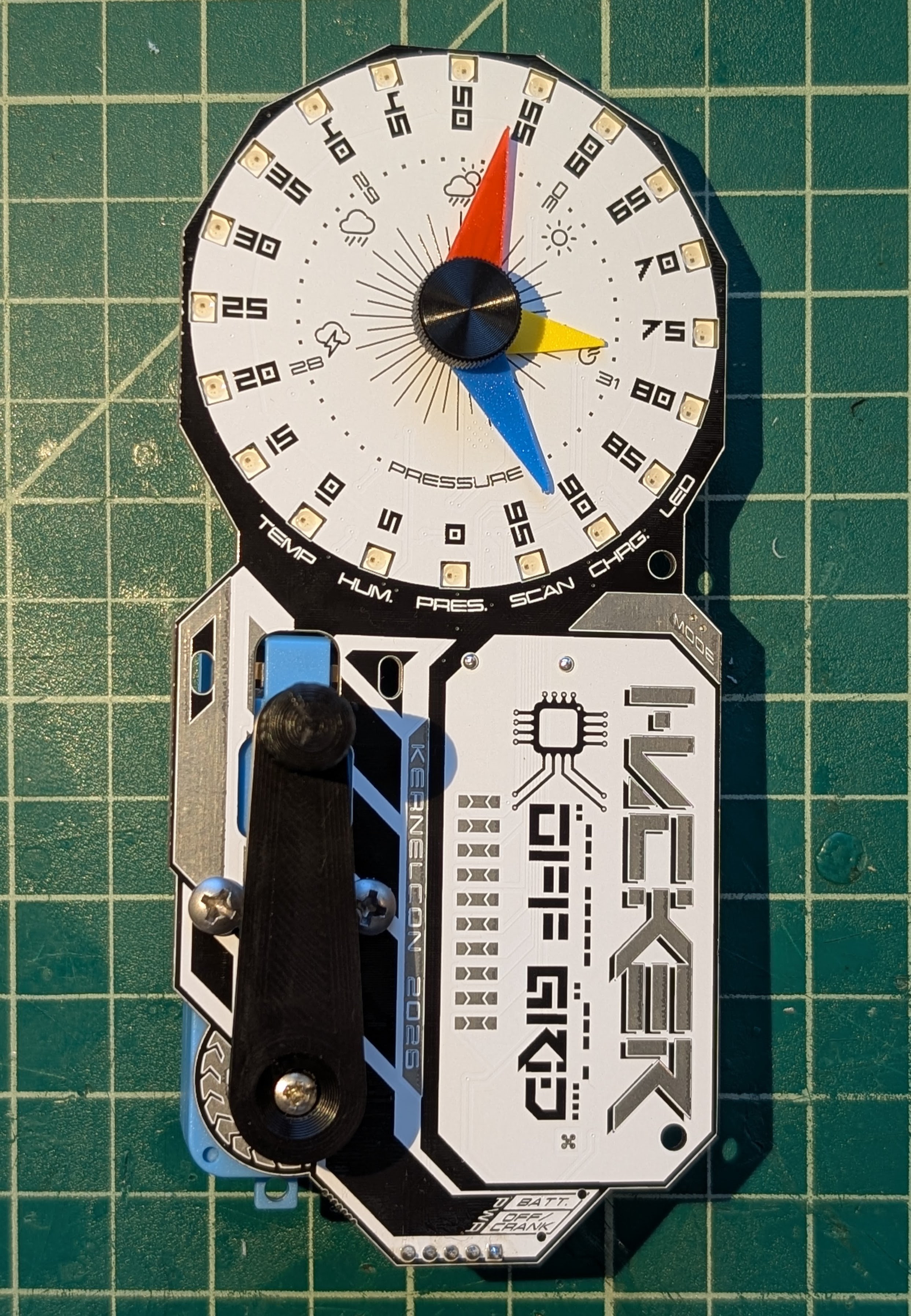
Your initial assembly is complete!
Quest
Ready to embark on an interactive, narrative-driven adventure? The badge is your gateway to a quest that will take you all over the conference space, complete with challenges and tasks to be solved!
How It Works
There are kiosks scattered throughout the venue that will guide you on your journey—however, you must find the correct one for your current level. That's where SCAN mode comes in. It's a proximity scanner to help you locate your next kiosk. But be warned: it uses a lot of battery power, so use it sparingly!
Once you find the right kiosk, you'll need to build up a charge using CHRG mode. These are off-grid devices after all... they need to be powered! Simply enter the mode and crank until your meter is full, then insert the badge into the kiosk to proceed.
Each kiosk has a printer that will share more of the story, present you with clues, and give you tasks to complete next.
Rewards
As you complete quest levels, you'll unlock additional LED animation patterns for your badge! Use LED mode and rotate the crank to cycle through them.
Getting Started
Head to the Badge Village area and look for the sign that identifies the first kiosk.
Weather Training
Visit the Weather Training area to learn how to become an off-grid meteorologist! Touch screen kiosks will walk you through all of the sensor readings—temperature, humidity, and barometric pressure—and teach you how to use them to predict the weather.
Once you've completed your training, a series of simulations will test what you've learned. Can you predict what's coming based on the readings?
This area also features physical devices to demonstrate how the sensors work in real life: a heater, a pressure chamber, and a humidifier. Watch your badge react in real time!
USB Charge Module Kit
In this activity, you'll solder and assemble a small PCB that lets you harness the crank power of your badge to charge devices via a USB-A port. Follow the instructions below to build your own!
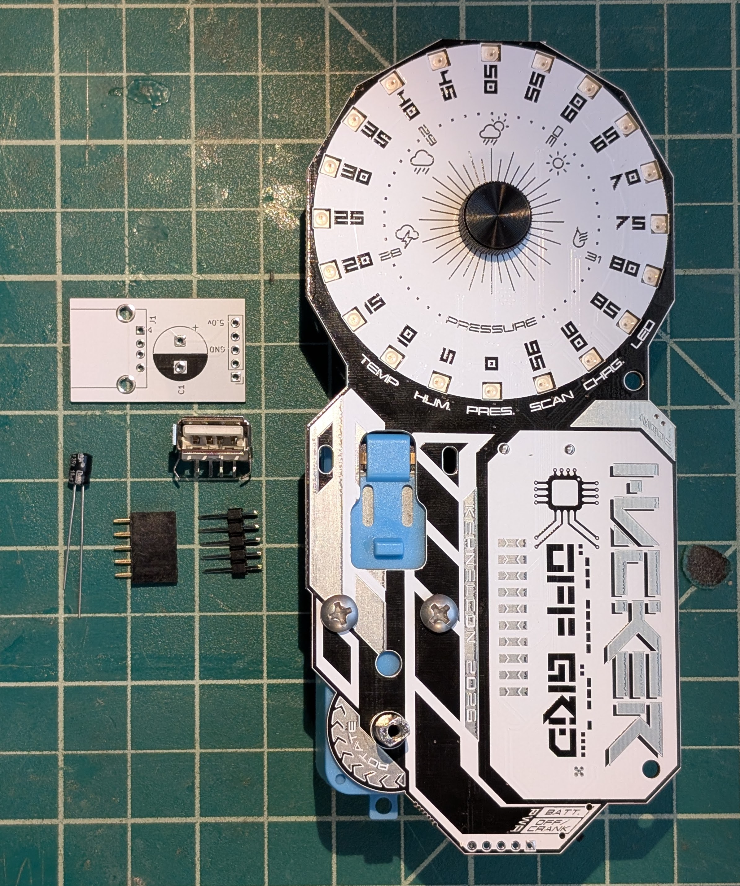
First, gather your parts from a volunteer at the badge village table:
- 1x blank PCB
- 1x capacitor
- 1x female header
- 1x male header
- 1x USB-A port
Click any image to enlarge.
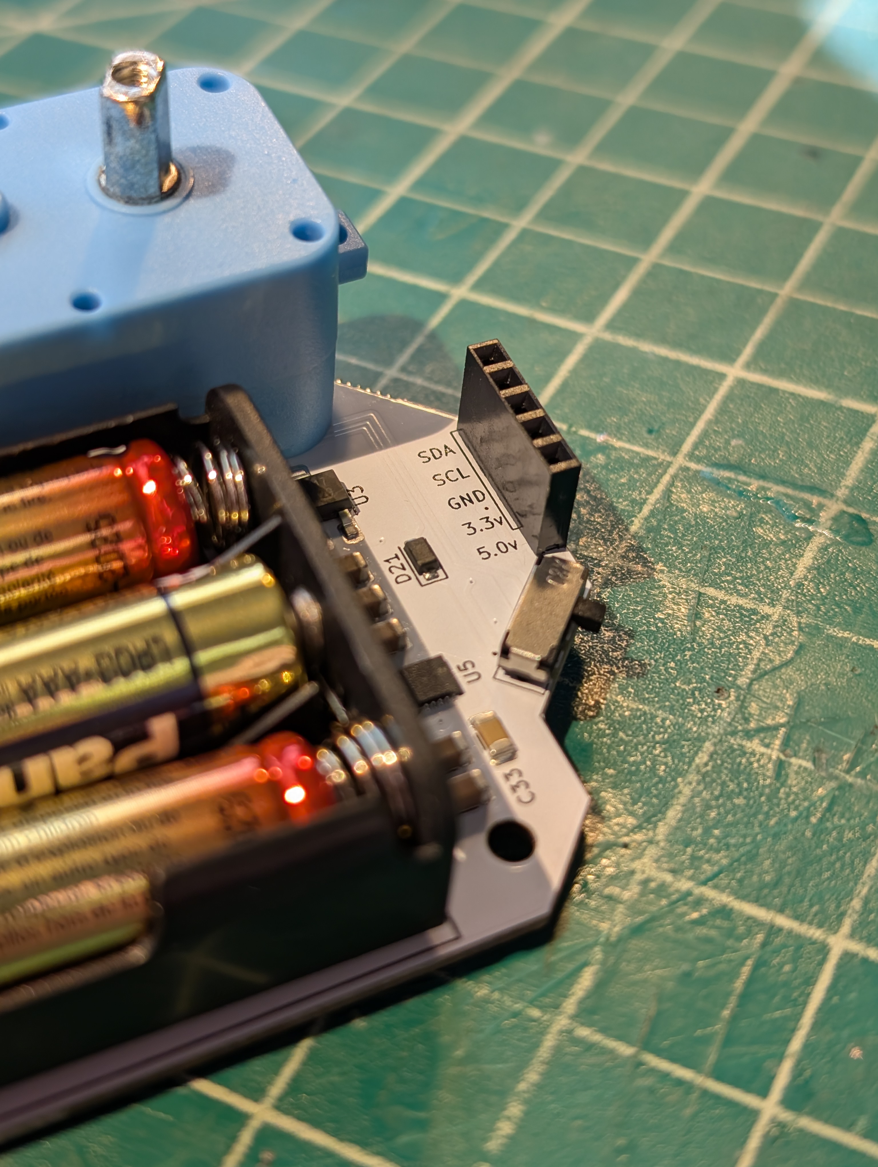
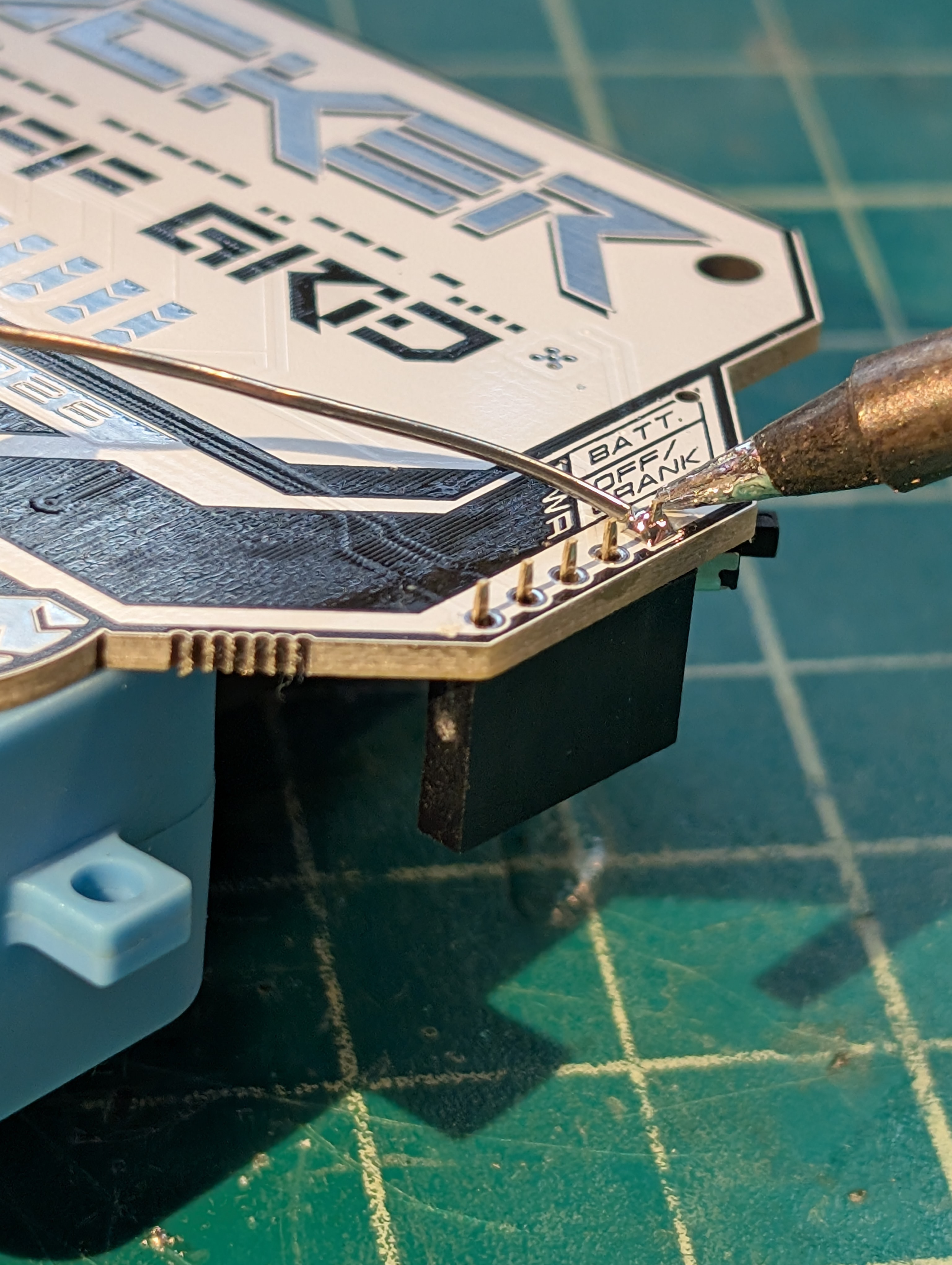
Next, insert the female header onto the back side of your badge as shown.
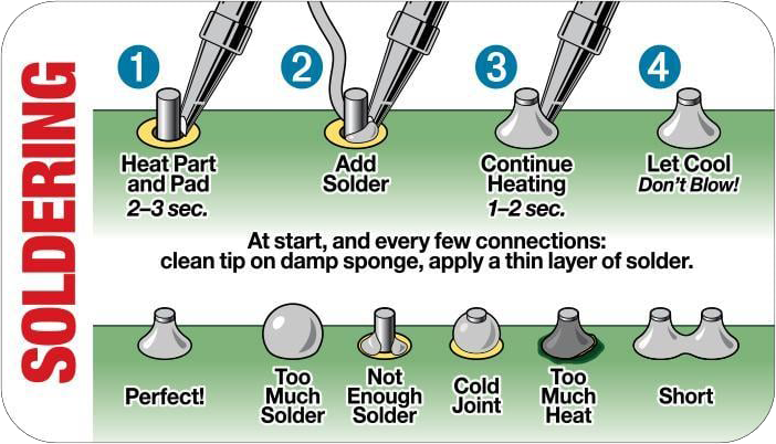
New to soldering? Here's a quick reference guide:
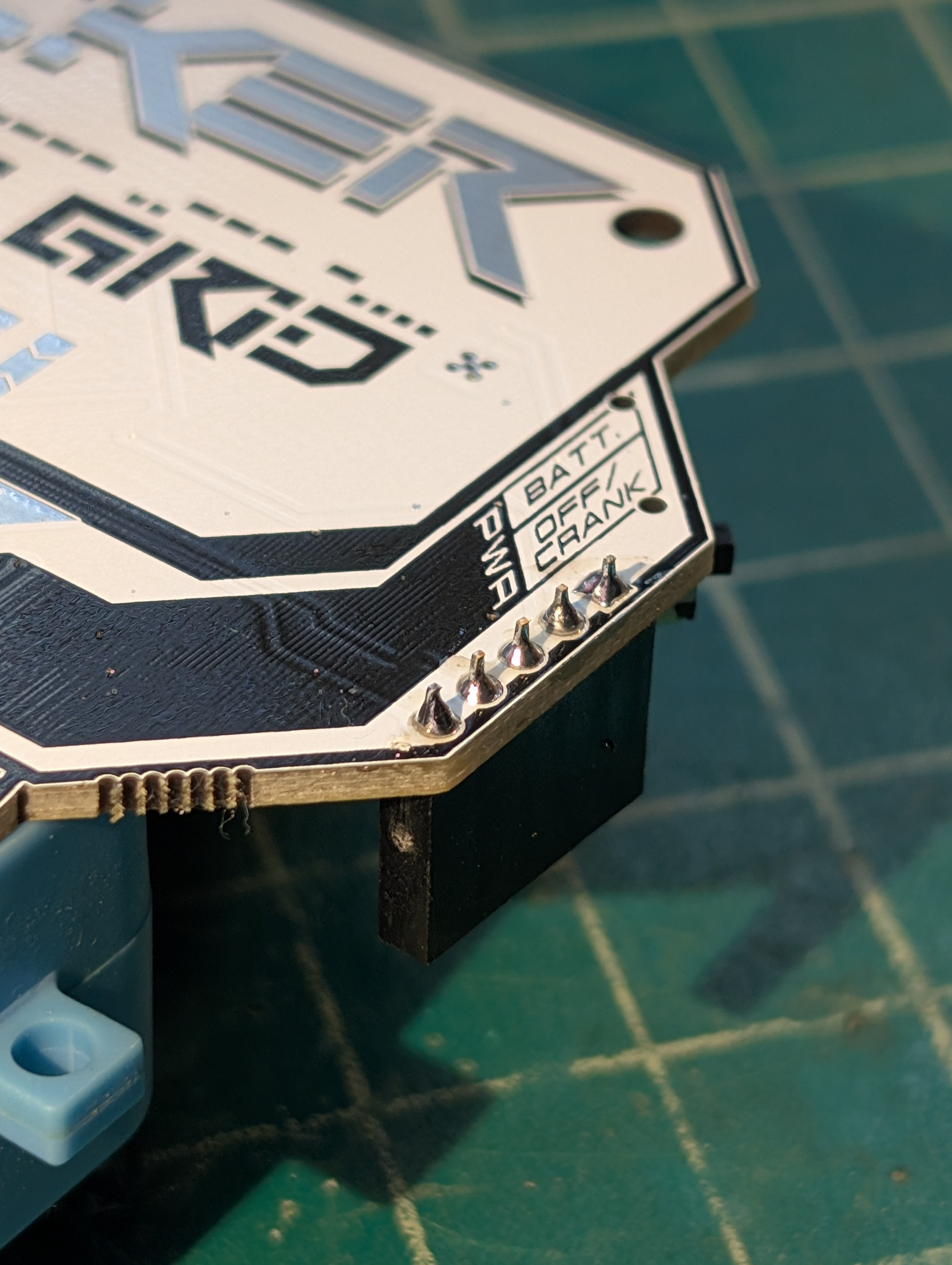
Now flip it over and, while pinching with your finger, solder one pin. Before soldering any more, make sure the header is aligned and flat on the PCB. With only one pin soldered, this is the easiest time to make adjustments.
Once aligned and flat, solder the rest of the pins.
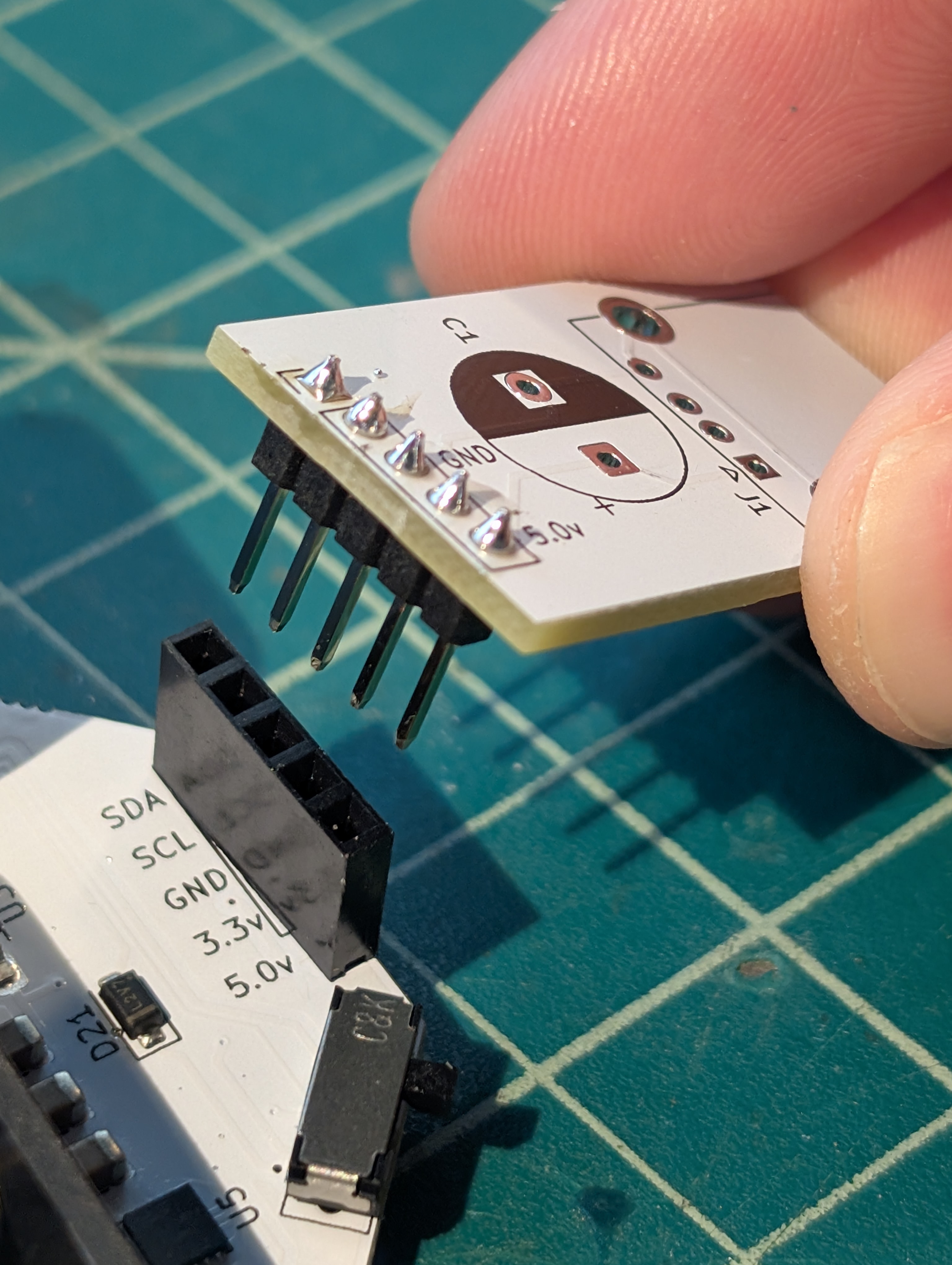
Now insert the male header into the female header as shown.
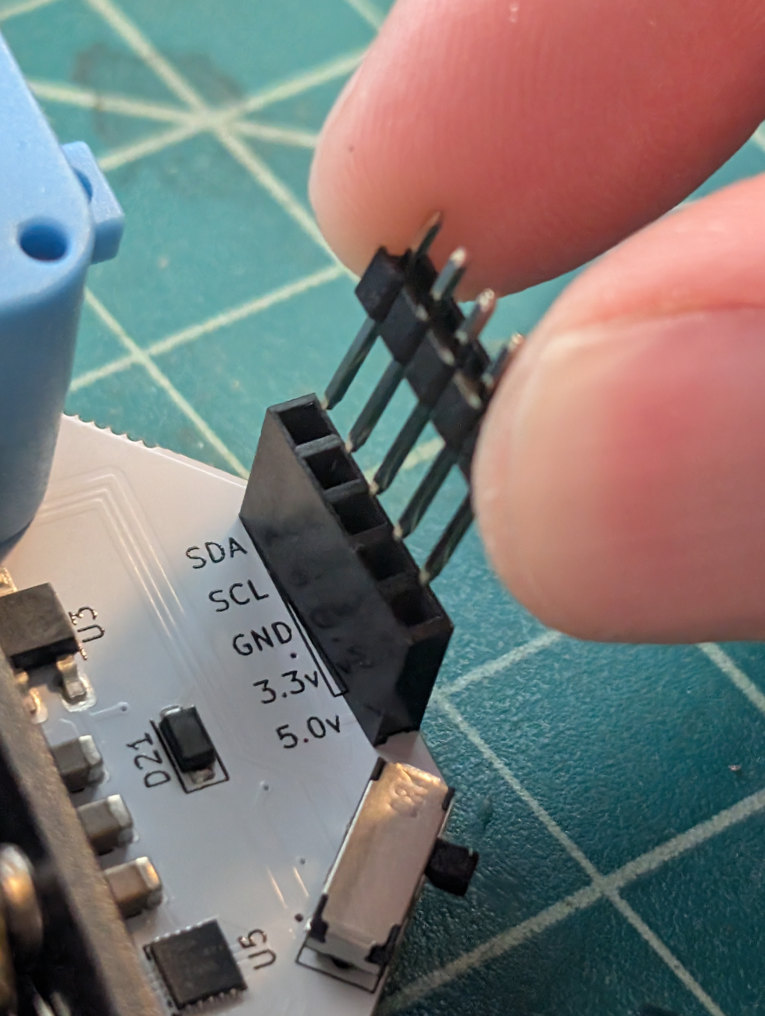
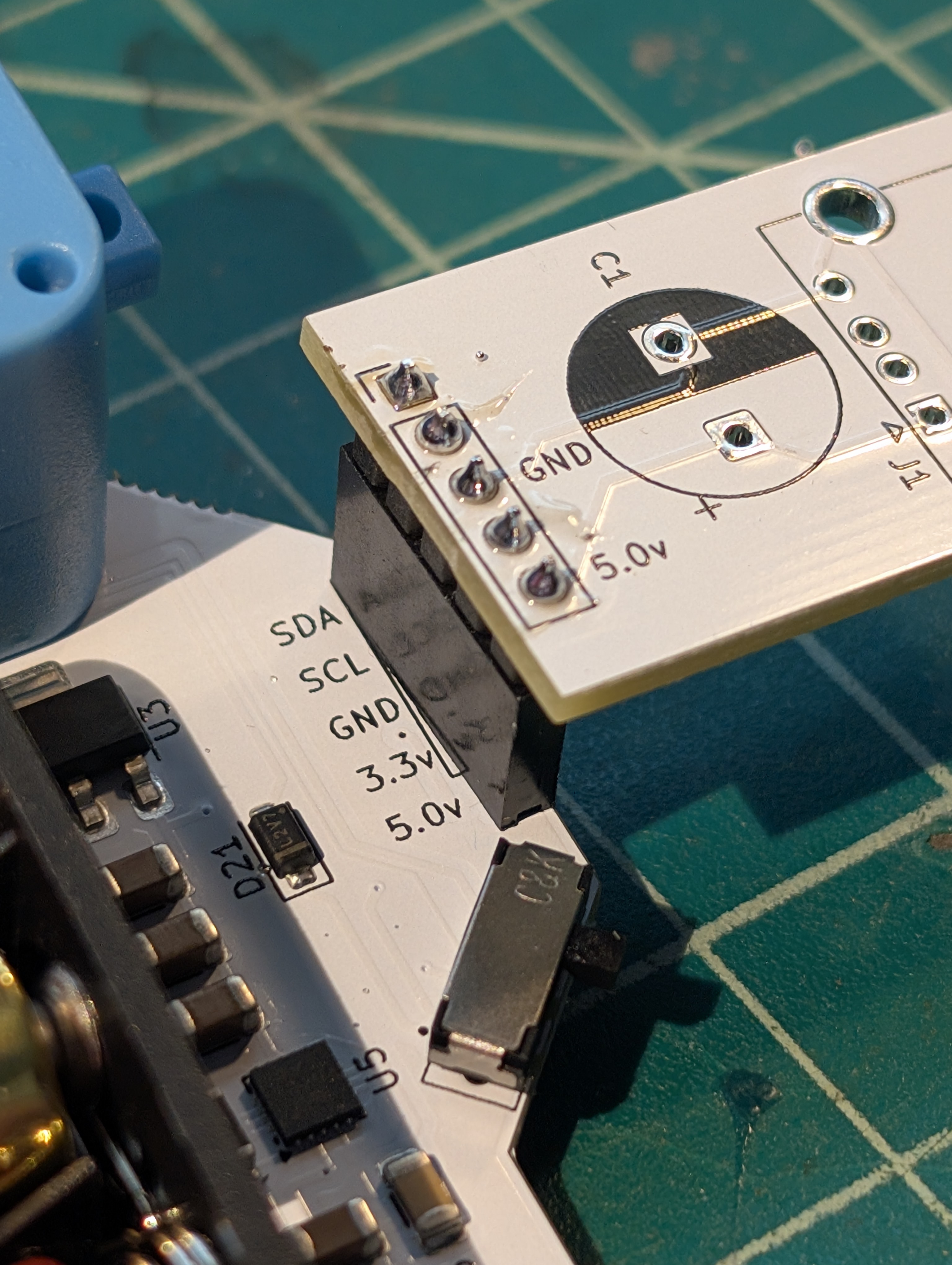
Next, insert the blank PCB. Note the pin alignment—make sure GND goes to GND and 5V goes to 5V.
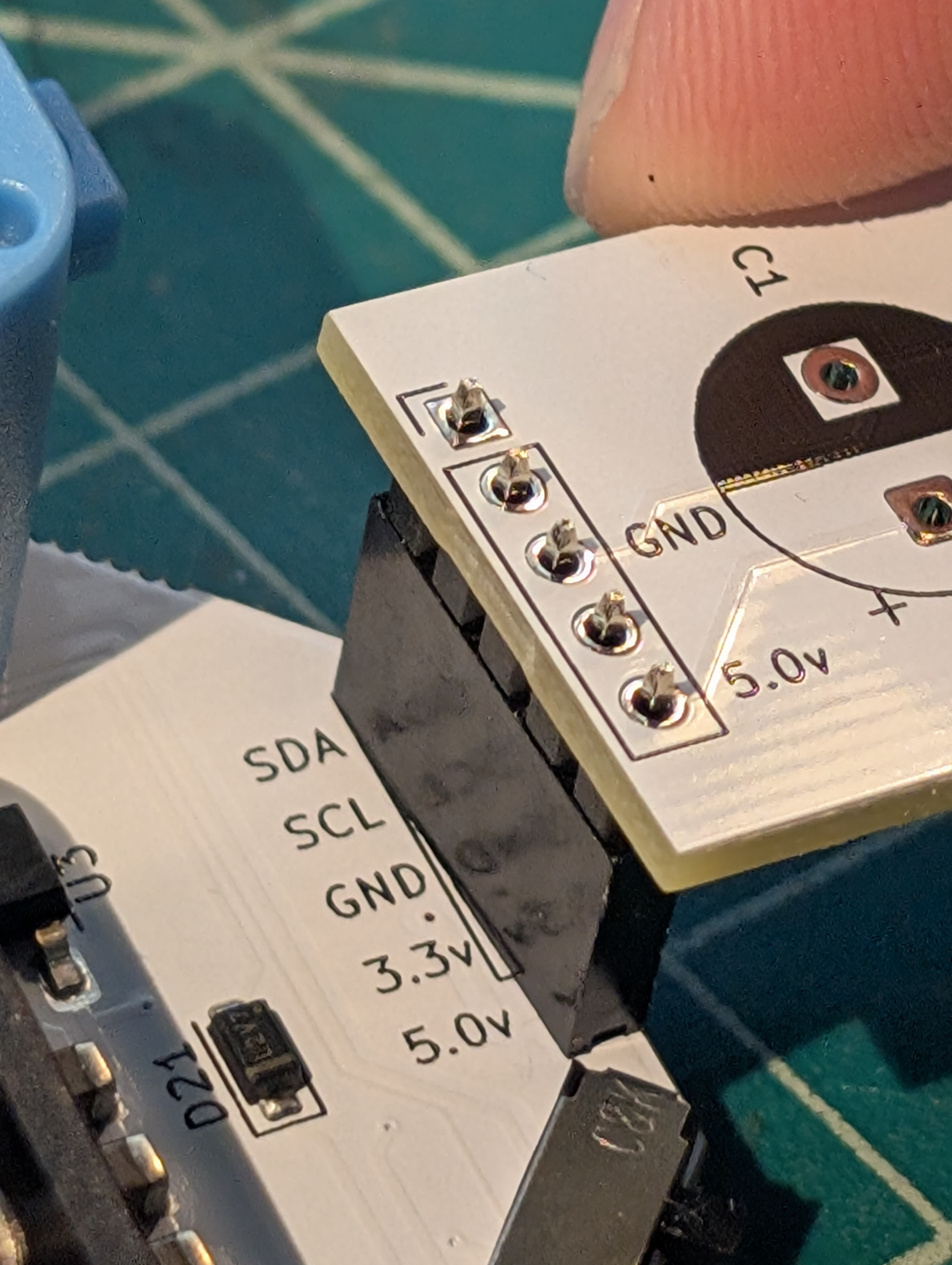
Again, start by soldering one pin and ensuring it's aligned and flat before proceeding to solder the rest of the pins.
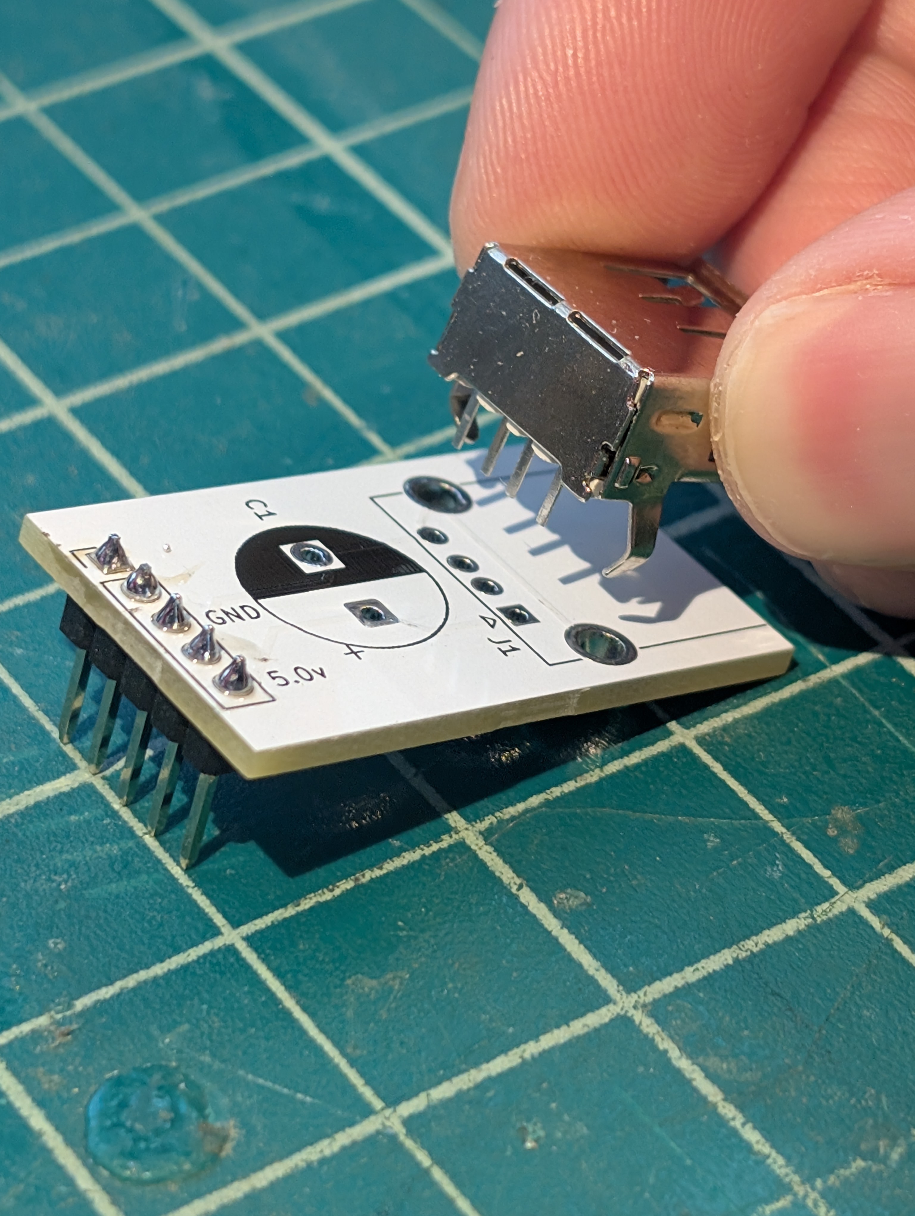
Nice job! Now remove the PCB with the header attached. We'll populate the rest of the components on it.
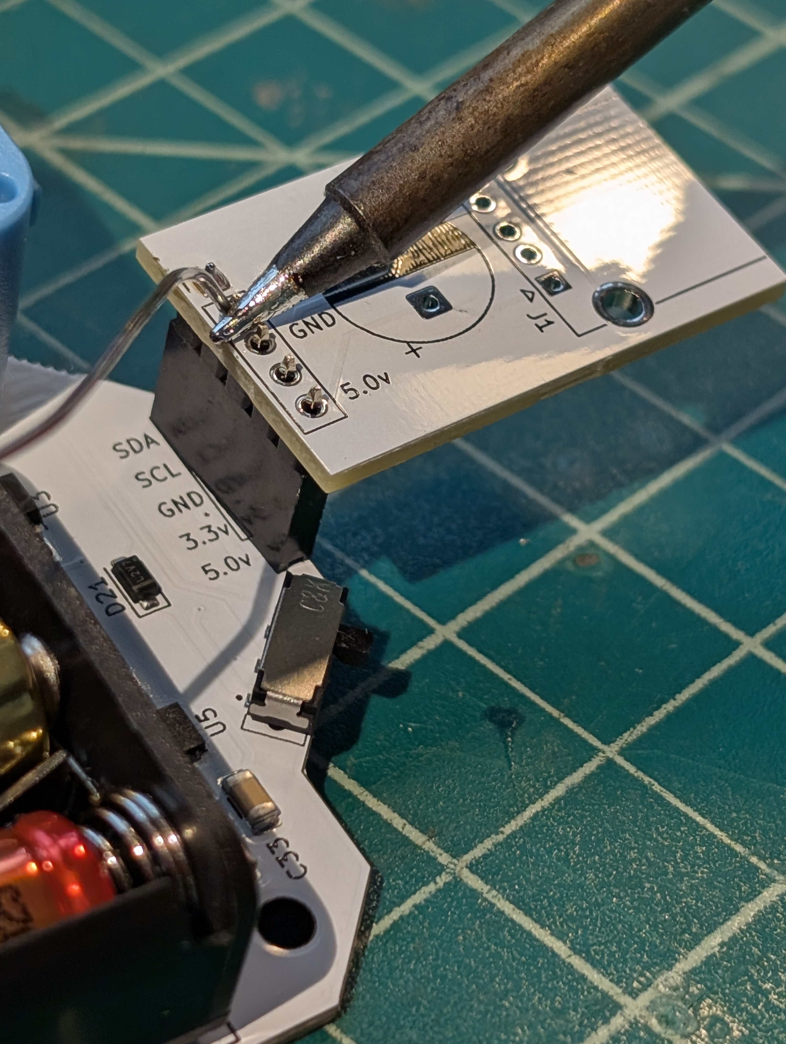
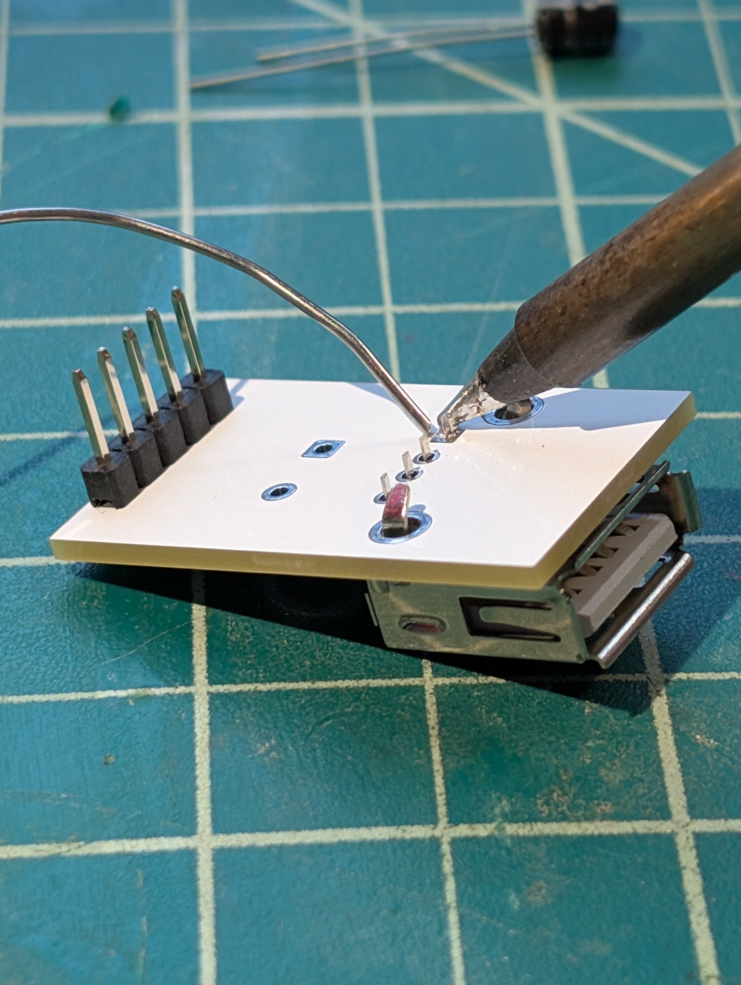
First, we're going to add the USB-A port. Insert the port onto the PCB, being careful to align all the pins before pressing too firmly—it may take a little finesse.
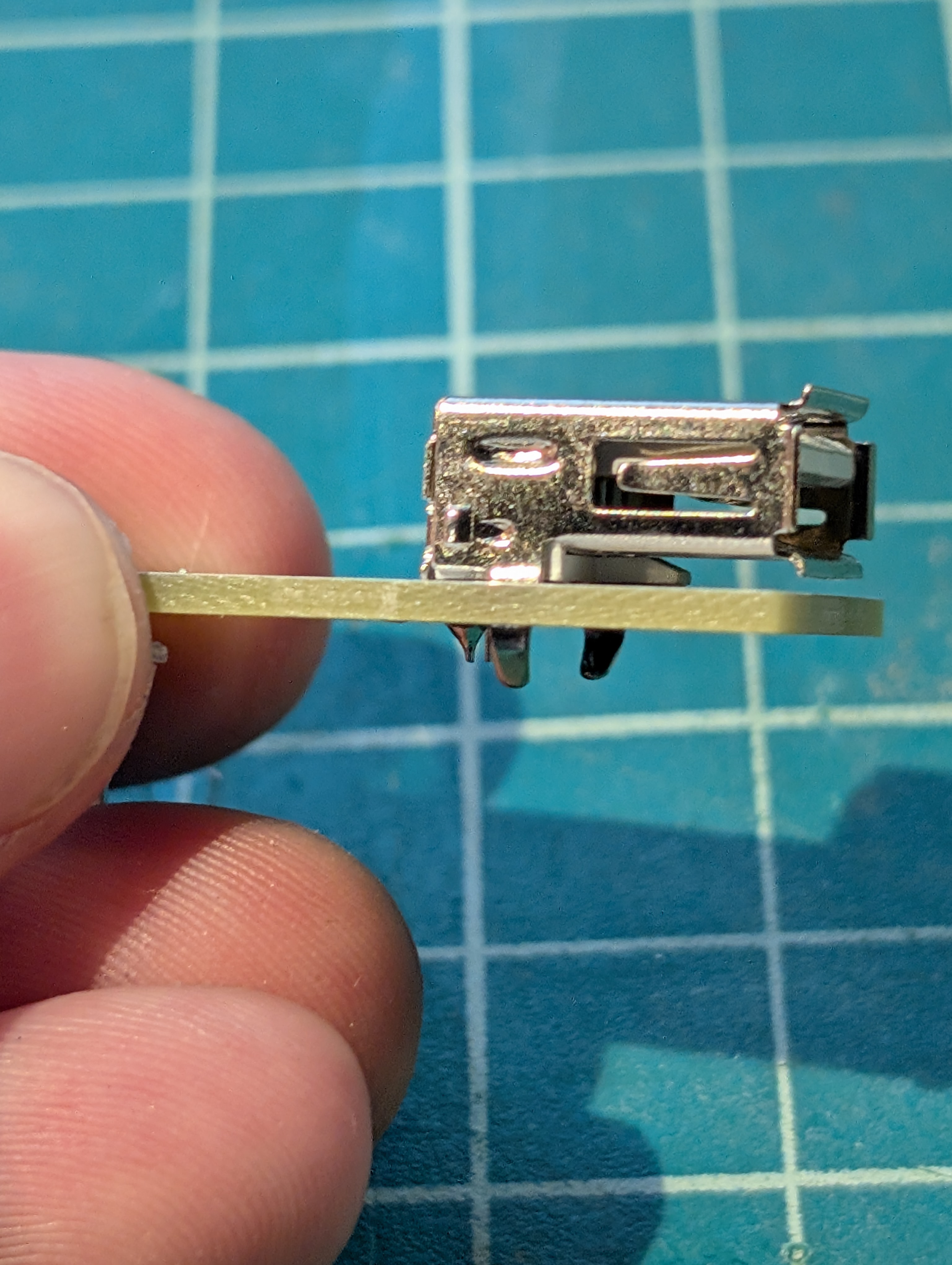
Now solder one pin. Like before, this is the easiest time to make sure the port is aligned and flat. Check it from the side to ensure it's exactly where you want it.
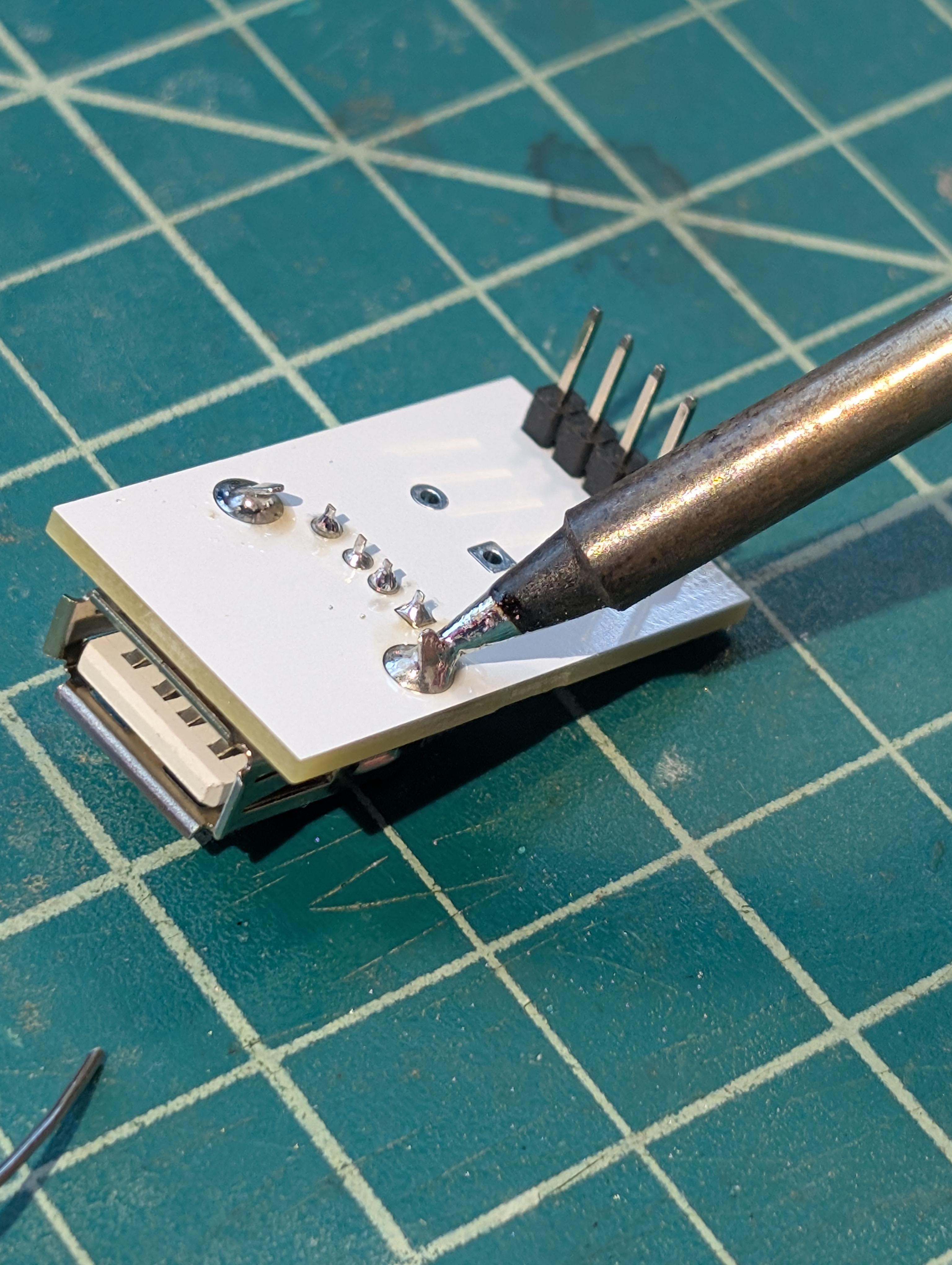
Now solder the rest of the pins.
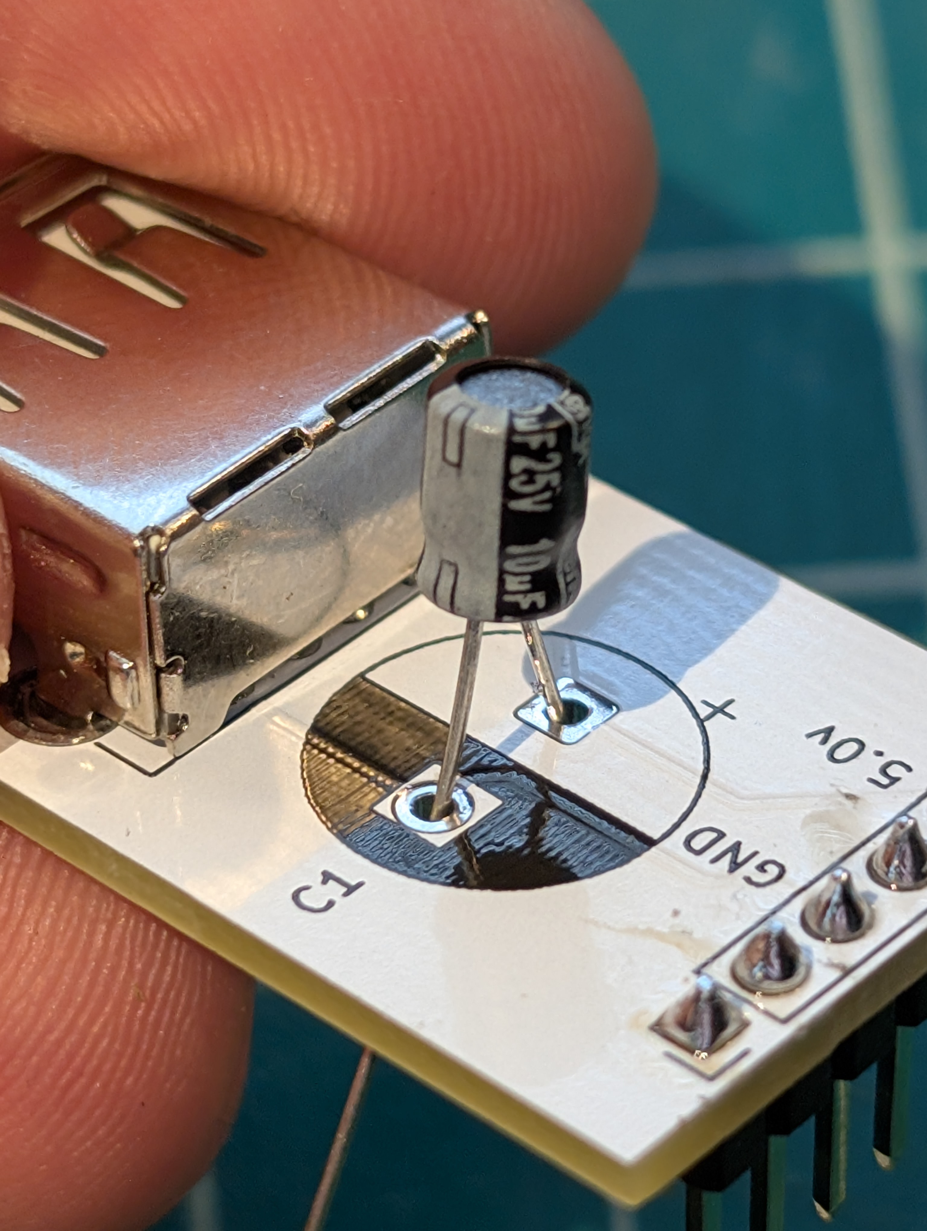
Next, we're going to place the capacitor. This capacitor helps keep the voltage stable and smooth. Note the polarity markings—the capacitor has a white line to indicate its negative side, and the PCB has a plus sign to mark the positive side.
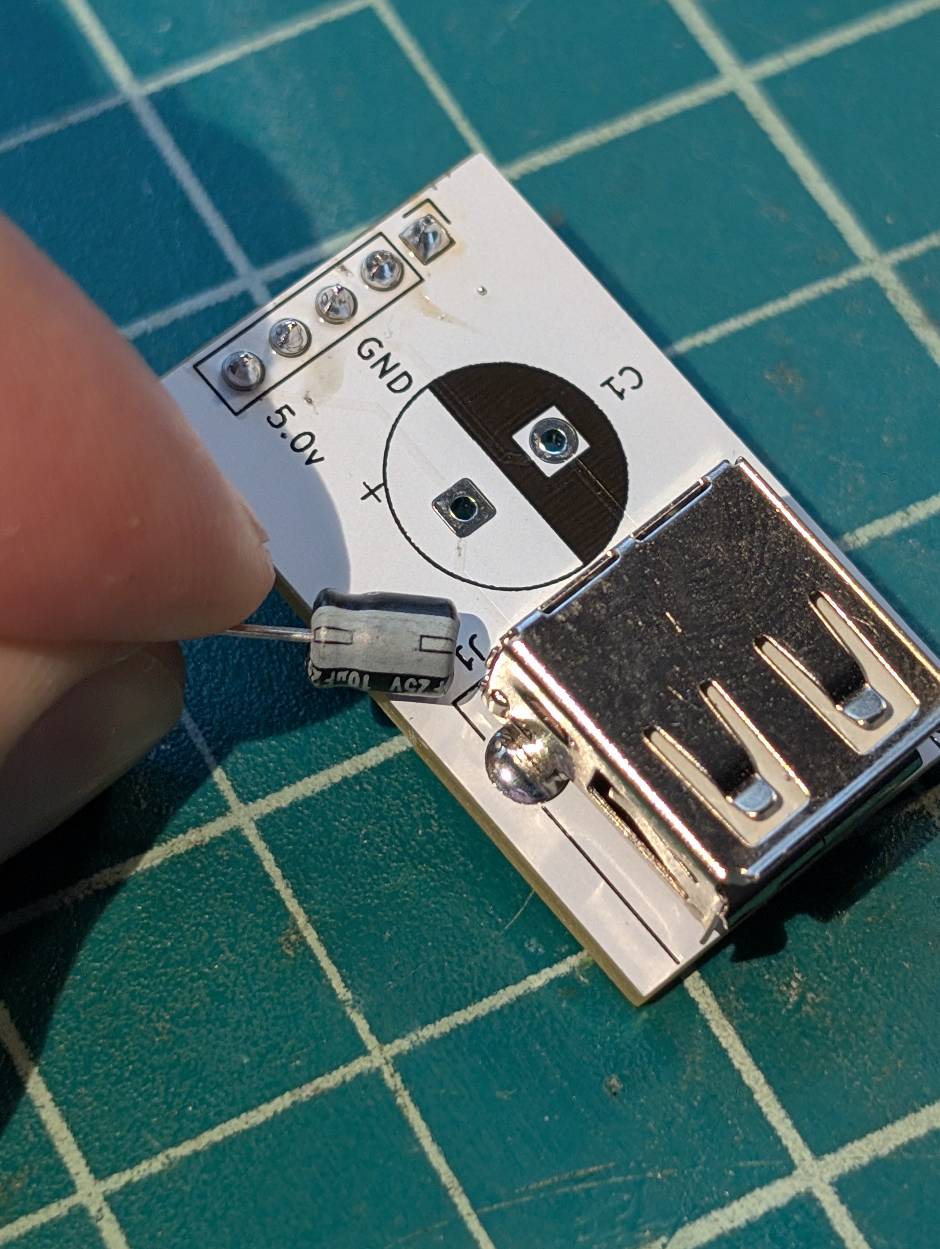
Insert the capacitor, ensuring the polarity is correct.
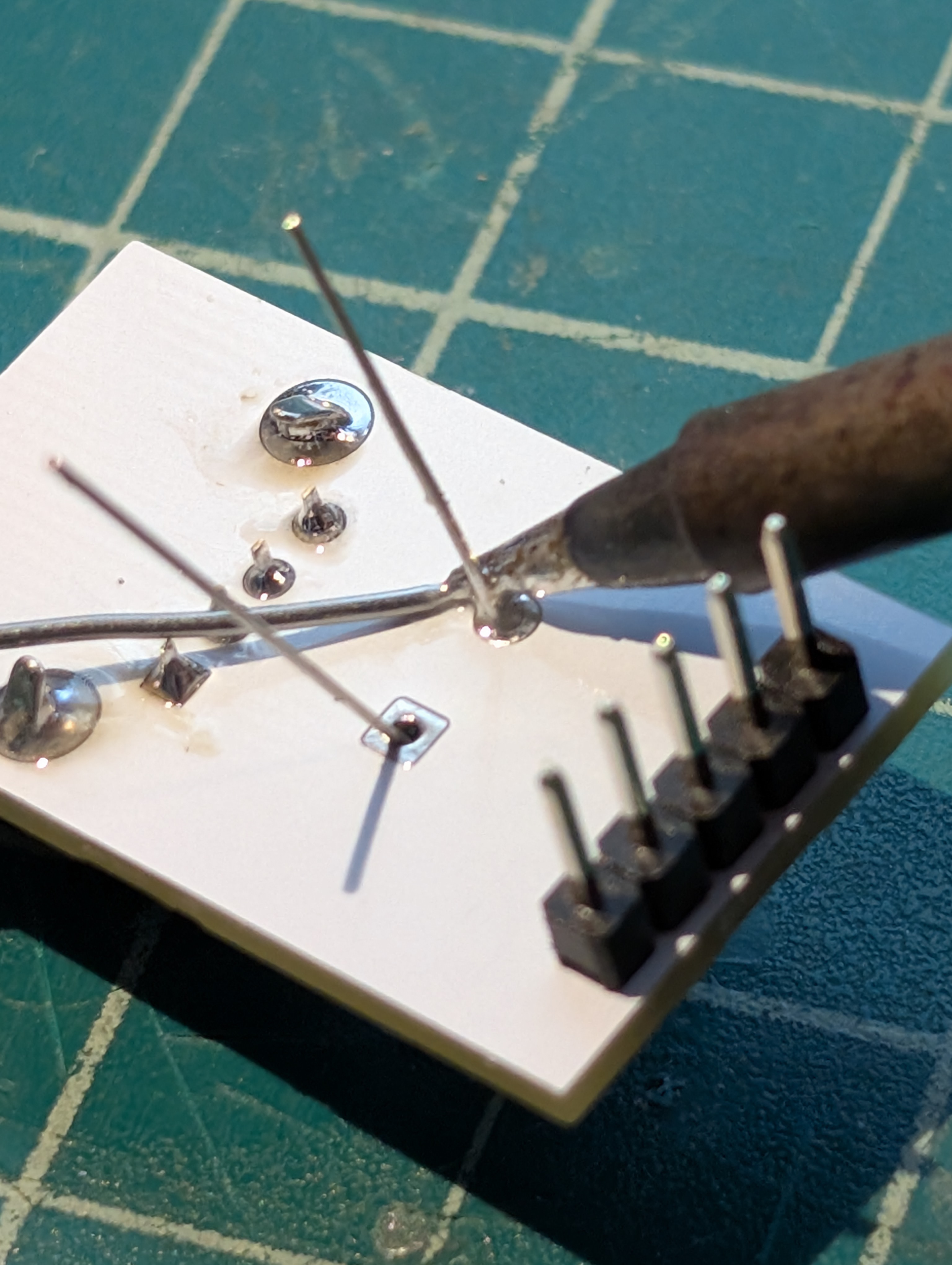
Now flip the board over and solder the legs of the capacitor.
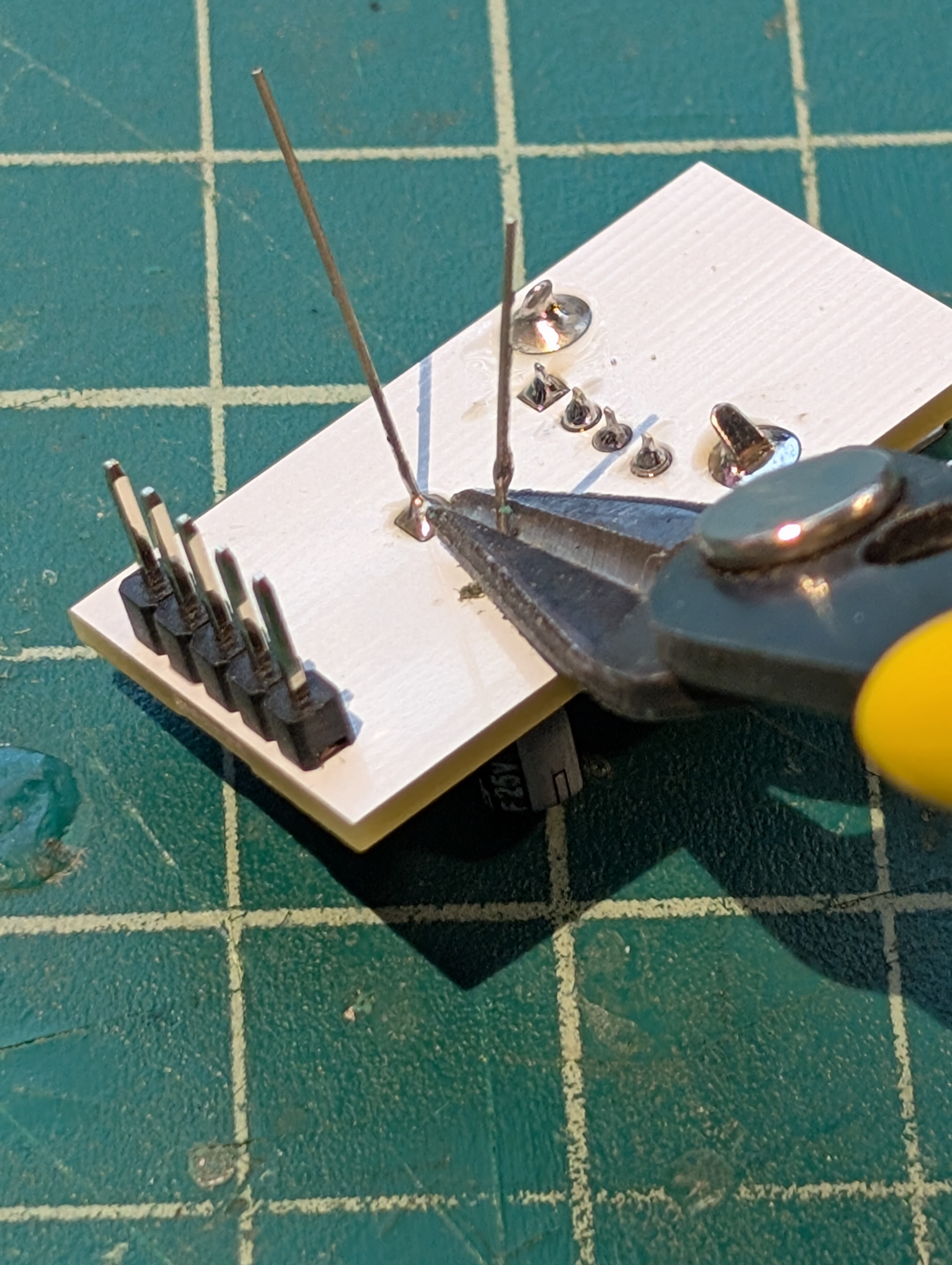
Now use some clippers to clip the excess length off. Note: clip just above the solder.
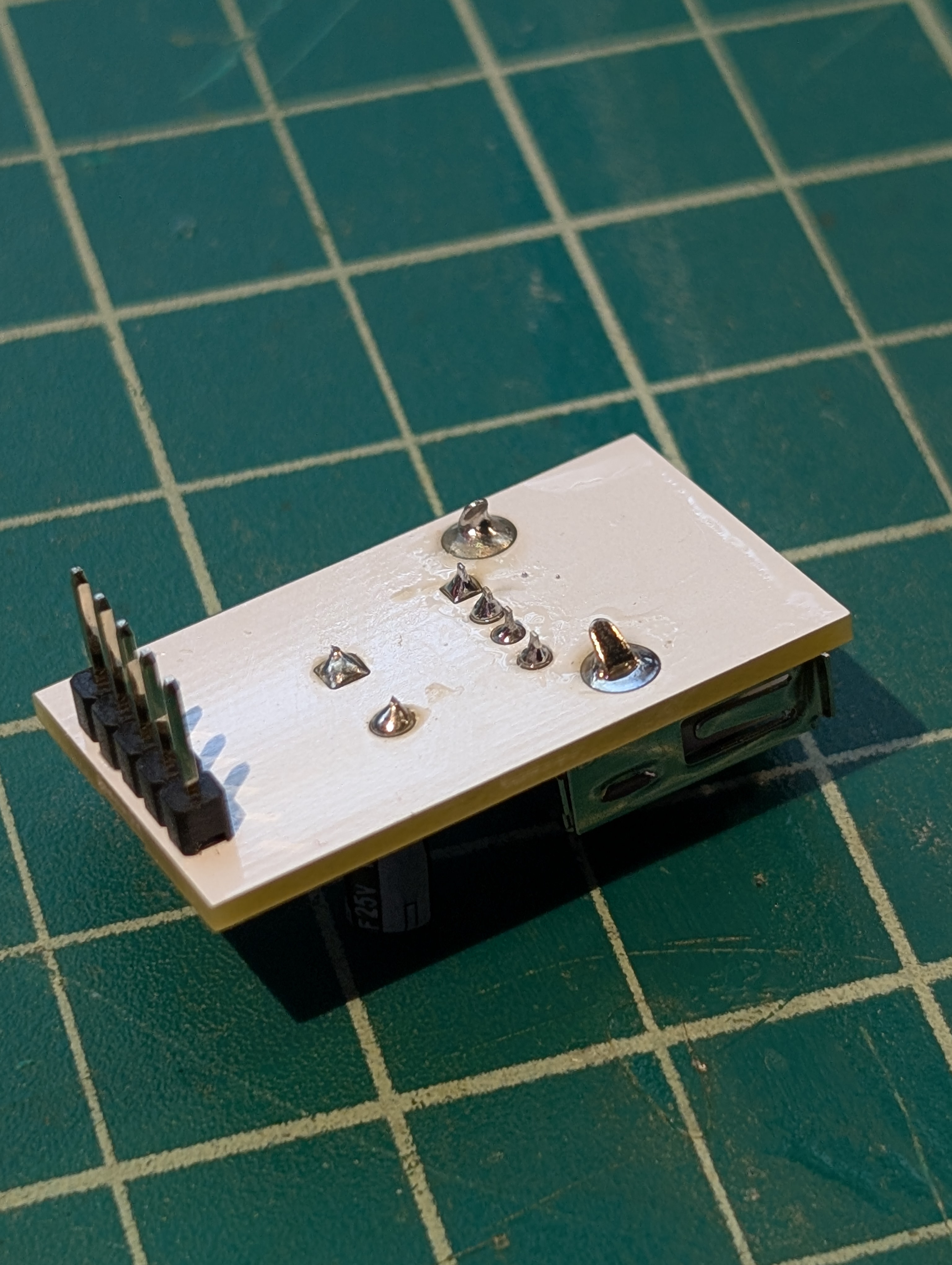
You did it! The board is now complete.

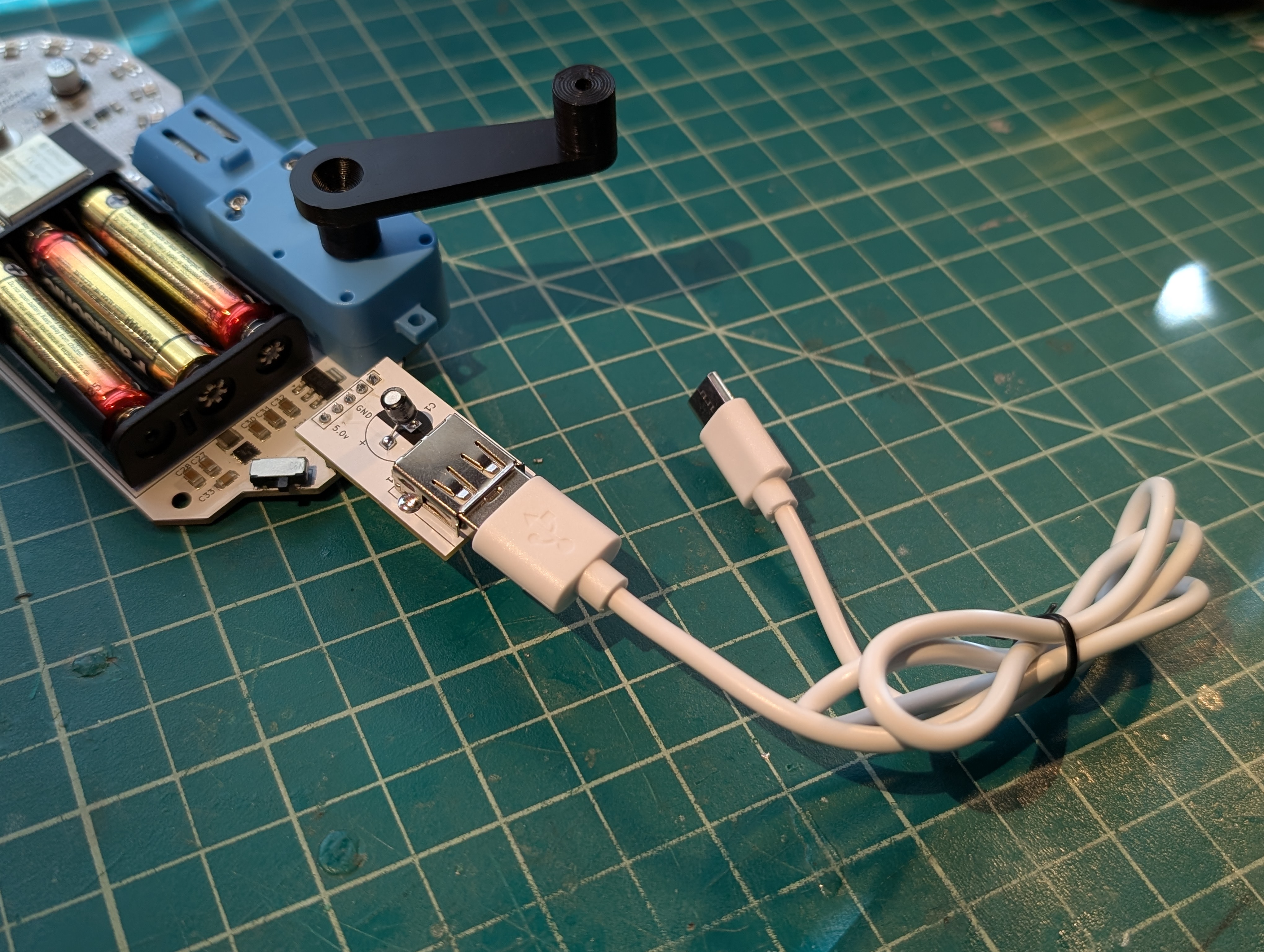
Nothing left to do but give it a test!